Electrical clip connector comprising expandable barrel segment

a technology of expandable barrel segments and connectors, which is applied in the direction of conductive connections, connections effected by permanent deformation, connection contact materials, etc., can solve the problems of increased maintenance and labor expenses, false torque readings, and bad connections, so as to prevent damage or deformation of terminal clips and enhance ergonomics

Inactive Publication Date: 2005-03-29
DELPHI TECH INC
View PDF26 Cites 3 Cited by
  • Summary
  • Abstract
  • Description
  • Claims
  • Application Information

AI Technical Summary

Benefits of technology

An electrical clip connector has a terminal clip which is electrically mated to a ground stud by hand. The terminal clip is protected by an erogonomically friendly housing which supports the functional requirements of the terminal clip. The housing has a hoop portion which defines a through hole orientated concentrically to a bore defined by a resilient barrel segment of the terminal clip. Communicating transversely with the through hole is a channel carried by a first portion of the housing which encases a first arm of the terminal clip engaged to a circumferential first end of the barrel segment. A second or activation arm of the terminal clip extends from an opposite end of the barrel segment and crosses over the first arm so that compression of the arms toward one-another causes the barrel segment to enlarge for receipt of the ground stud. The second arm is encased by a second portion of the housing which is preferably hinged to the first portion near the hoop portion. When the clip connector is fully compressed, contact between the first and second portions prevent damage or deformation of the terminal clip which could degrade the electrical connection.
Advantages of the present invention include a clip connector having a novel housing which protects a terminal clip from inadvertent damage due to over deflection, provides consistent deflection regardless of wire gauge size, protects surrounding wires from insulation chaffing, and enhances the ergonomics making the connector user friendly in the assembly plant.

Problems solved by technology

Unfortunately, inadvertent mis-alignment of the nut to the threaded stud can cause cross-threading between the nut and the stud which will cause a false torque reading and potentially a bad connection.
Moreover, tools such as a nut driver are cumbersome within a manufacturing environment and lead to increase maintenance and labor expenses.
Unfortunately, the exposed state of the metallic terminal clip leaves it prone to damage from adjacent obstacles.
Moreover, the sharp edges and snagging interfaces of the terminal clip can snag adjacent wires causing wire insulation chaffing or which may prevent the activation arm from fully releasing after being depressed.
Moreover, if the activation arm is depressed to far, the terminal clip may be inadvertently damaged via plastic deformation, loosing some of its resiliency necessary to provide a reliable electrical connection.
Yet further, the activation arm is not ergonomically friendly to the user in the assembly plant and in its exposed condition is susceptible to damage due to shipping and handling.

Method used


Image

  • Electrical clip connector comprising expandable barrel segment
  • Electrical clip connector comprising expandable barrel segment
  • Electrical clip connector comprising expandable barrel segment

Examples


Embodiment Construction

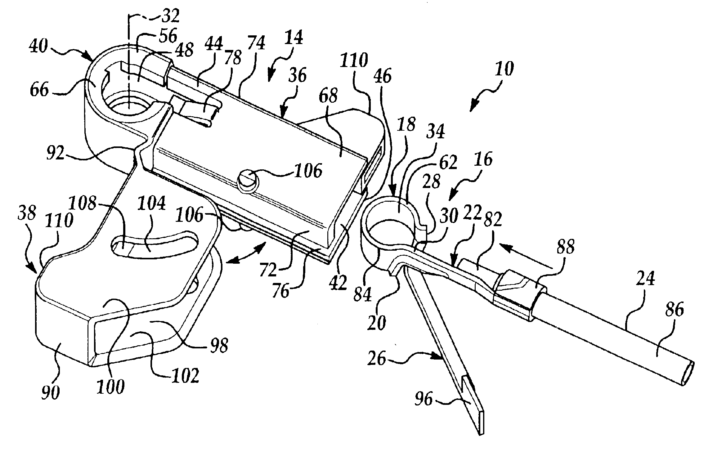
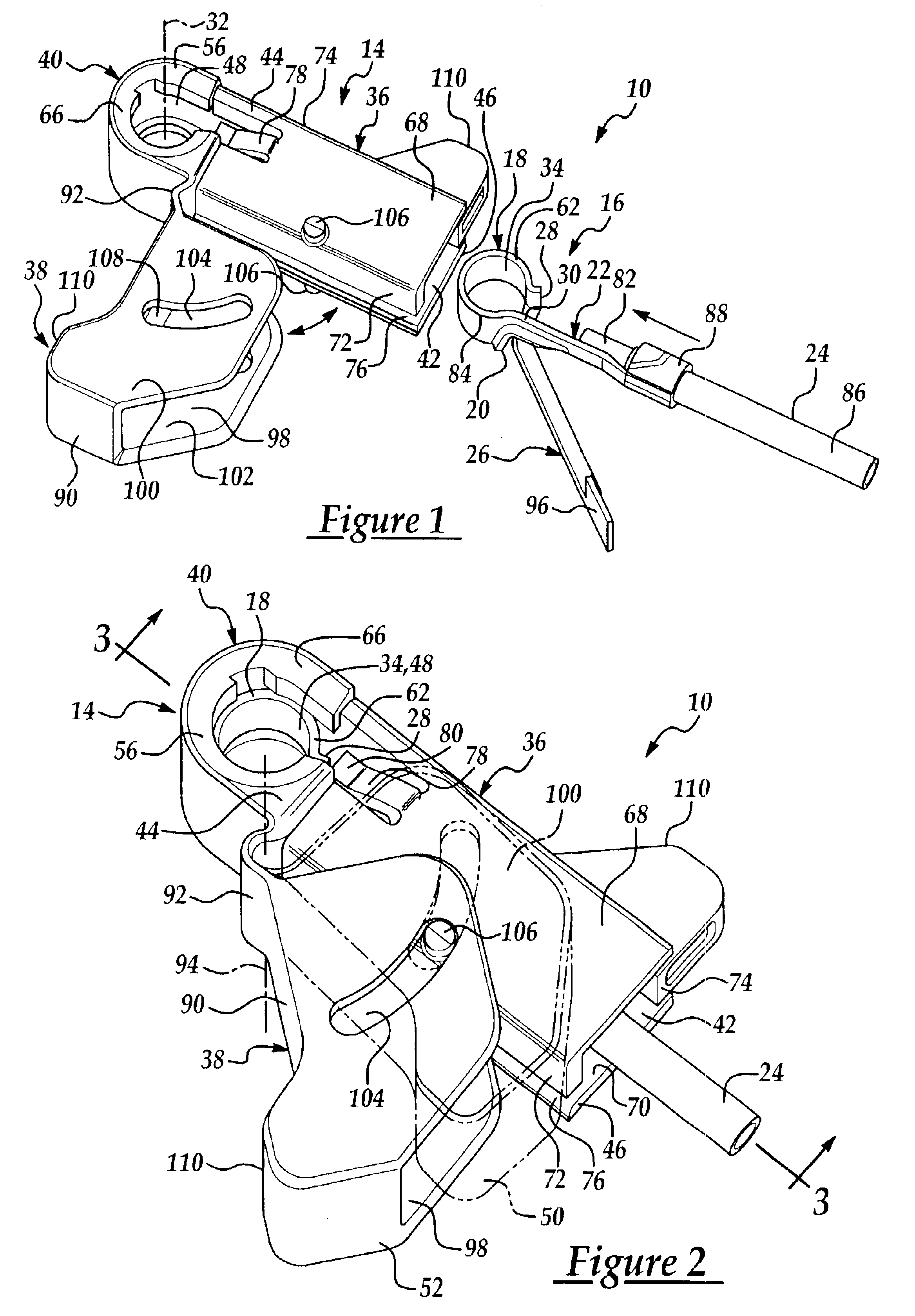
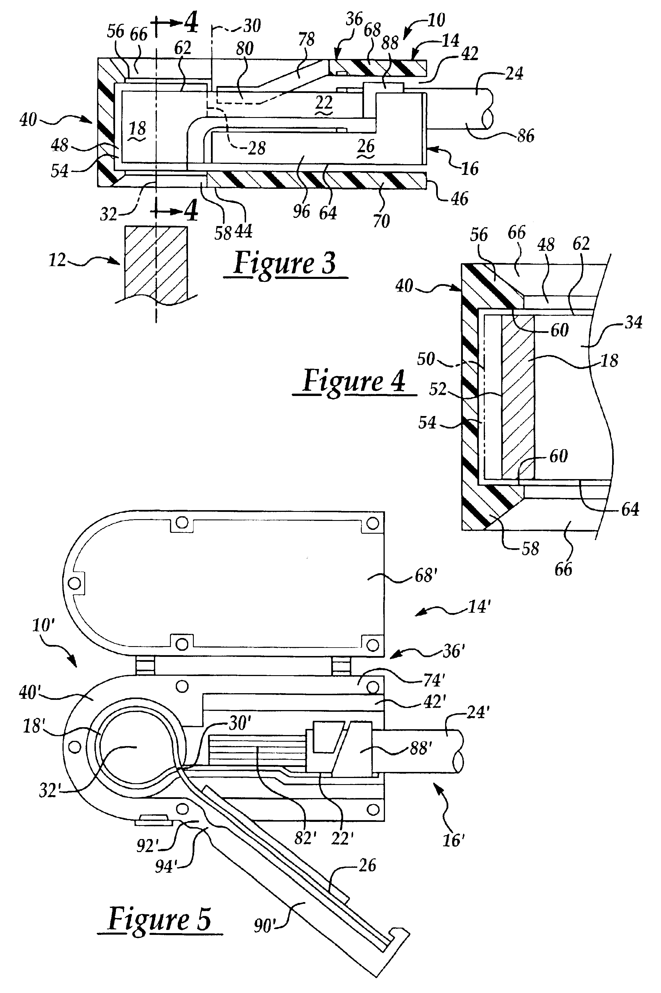
Referring now to the drawings, FIGS. 1-3 illustrate an electrical clip connector 10 capable of securing electrically to a protruding ground stud 12 preferably within an automotive environment. The clip connector 10 has a housing 14 which substantially encases a terminal clip 16 capable of repeated matings to the ground stud 12, with a repeating predefined normal force, by hand and without the use of tools. The terminal clip 16 has a barrel segment 18 which wraps circumferentially about the stud 12 at slightly less than three hundred and sixty degrees to electrically engage the stud. A first end 20 of the barrel segment 18 engages unitarily to a radially outward projecting first arm 22 that engage electrically to an insulated wire 24. A second or activation arm 26 projects substantially tangentially from the barrel segment 18 and outward from a second end 28 of the barrel segment 18, thus crossing under the first arm 22 at an intersection or crossing point 30 located radially outward...


PUM


Abstract

An electrical clip connector has a terminal clip which is electrically mated to a ground stud by hand. The terminal clip is protected by an erogonomically friendly housing which supports the functional requirements of the terminal clip. The housing has a hoop portion which defines a through hole orientated concentrically to a bore defined by a resilient barrel segment of the terminal clip. Communicating transversely with the rough hole is a channel carried by a first portion of the housing which encases a first arm of the terminal clip engaged to a circumferential first end of the barrel segment. A second or activation arm of the terminal clip extends from an opposite end of the barrel segment and crosses over the first arm so that compression of the arms toward one-another causes the loop segment to enlarge for receipt of the ground stud. The second arm is encased by a second portion of the housing which is preferably hinged to the first portion near the hoop portion. When the clip connector is fully compressed, contact between the first and second portions prevent damage or deformation of the terminal clip which could degrade the electrical connection.

Description

TECHNICAL FIELDThe present invention relates to an electrical clip connector and more particularly to a ground electrical clip connector for an automotive ground stud.BACKGROUND OF THE INVENTIONConventional electrical grounding methods within the automotive industry include a connection having a ring terminal held to a threaded stud with a threaded nut. The electrical contact is created between the ring terminal and the body sheet metal by applying torque to the nut which applies an axial force upon the ring terminal. Thus a reliable connection is dependent upon the amount of torque applied to the nut. Because this is controlled in the power nut driver used at the assembly plant, frequent calibration of the nut driver is required to assure compliance to the torque specification. Unfortunately, inadvertent mis-alignment of the nut to the threaded stud can cause cross-threading between the nut and the stud which will cause a false torque reading and potentially a bad connection. Moreo...

Claims


Application Information

Patent Timeline
Patent Type & Authority Patents(United States)
IPC IPC(8): H01R4/48H01R4/64H01R4/18H01R4/02H01R4/10
CPCH01R4/646H01R4/48H01R4/023H01R4/029H01R4/185
Inventor DAUGHERTY, JAMES D.NADASKY, THOMAS M.
Owner DELPHI TECH INC
Why Eureka
Try Eureka