Spinal implant connection assembly

a technology of spinal implants and connecting parts, which is applied in the field of spinal implant connection, can solve the problems of surgeons not wanting to exercise either of these options, and it is difficult to provide secure connections between the spinal support rod and these vertebral anchors, so as to reduce the profile of the spinal attachment system and reduce the physical mass

Inactive Publication Date: 2005-03-29
WARSAW ORTHOPEDIC INC
View PDF34 Cites 86 Cited by
  • Summary
  • Abstract
  • Description
  • Claims
  • Application Information

AI Technical Summary

Benefits of technology

An object of this invention is to reduce the physical mass that is typically required to attach a spinal rod to a vertebral anchor.
An advantage of this invention is that the clevis allows a vertebral anchor to be placed closer to the spinal rod than prior art designs that also use a single means to allow the surgeon to secure both the anchor and the rod to the connection assembly in one tightening step.
A feature of this invention is that it allows the surgeon the option of lowering the profile of a spinal attachment system closer to the spine without requiring the surgeon to sacrifice the capsule of a facet joint that may reside next to the connection assembly. In other words, this invention allows the connection assembly to be placed in a position that is medial to the facet joint.

Problems solved by technology

It is difficult to provide secure connections between the spinal support rod and these vertebral anchors at all the various angles that are required, especially where there are different distances between the rod and bolts and where these components are located at different heights on the patient.
Occasionally, however, the surgeon may not wish to exercise either of these options in a particular surgery.

Method used


Image

  • Spinal implant connection assembly
  • Spinal implant connection assembly
  • Spinal implant connection assembly

Examples


Embodiment Construction

Specific language is used in the following description to publicly disclose the invention and to convey its principles to others. No limits on the breadth of the patent rights based simply on using specific language are intended. Also included are any alterations and modifications to the description that should normally occur to one of average skill in this technology.

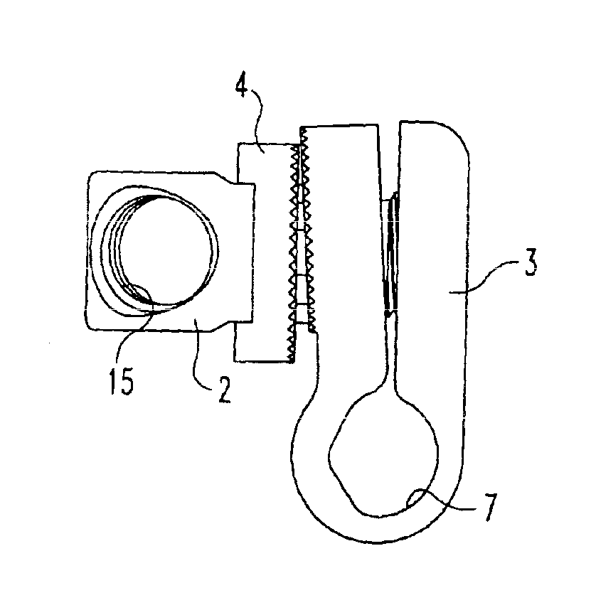
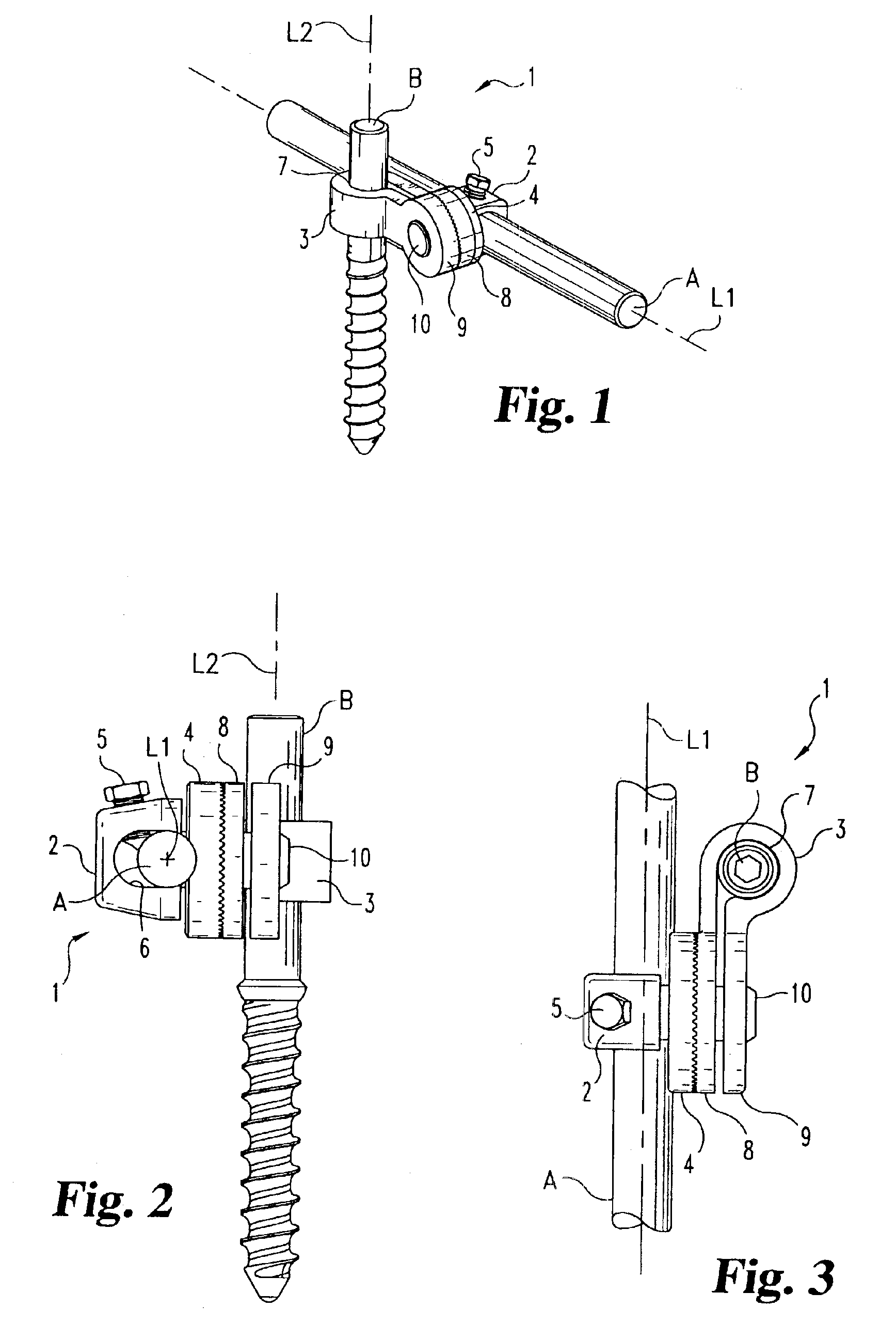
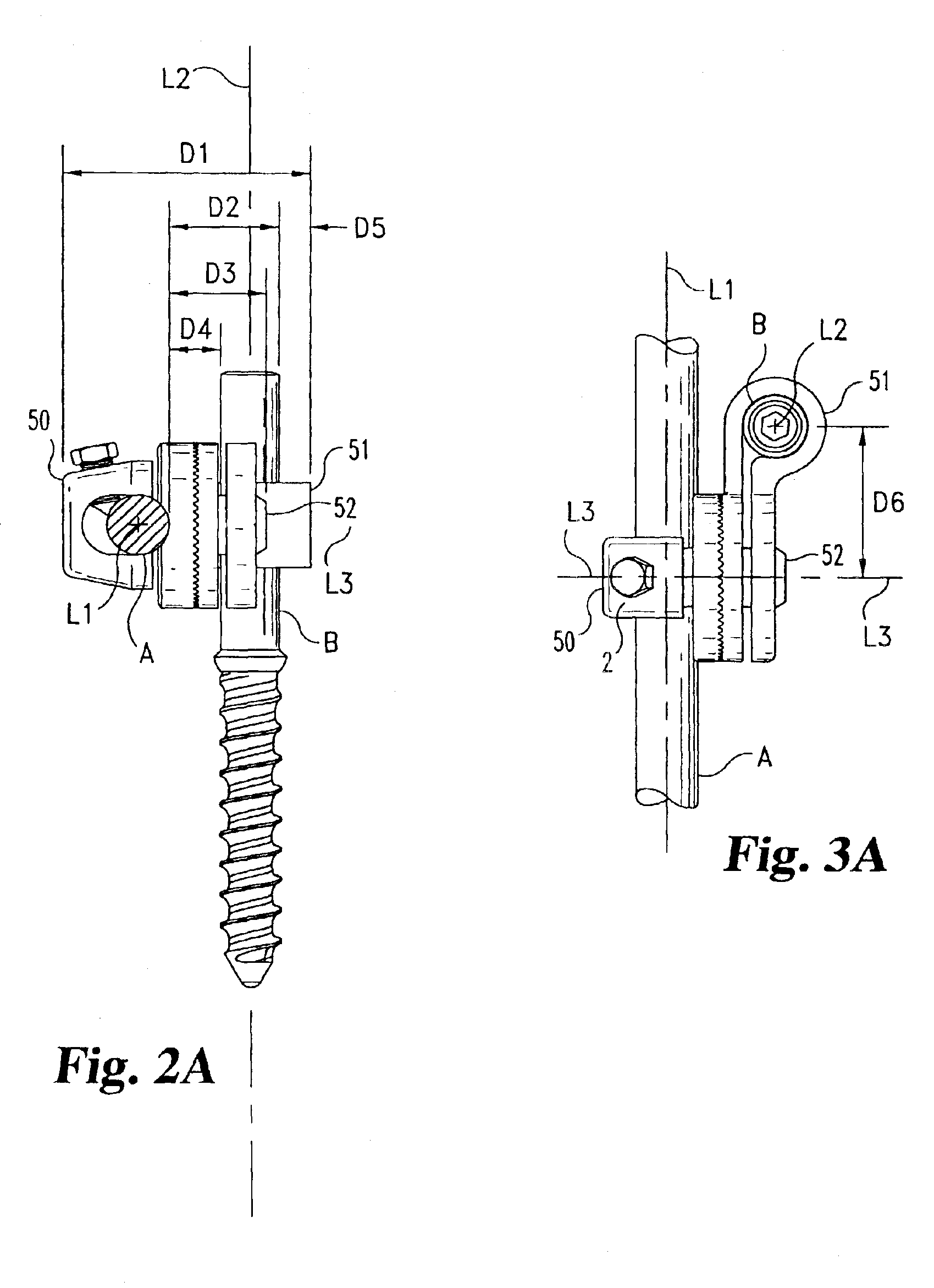
A connection assembly 1 according to the invention is shown in FIGS. 1-3. Connection assembly 1 is shown attaching a spinal implant rod “A” with a longitudinal axis L1 to the shaft of a vertebral anchor “B” with the longitudinal axis L2. Connection assembly 1 includes a bolt 2, a clevis 3, a rod interface washer 4, and a set screw 5. Bolt 2 has an aperture 6 for receiving a rod in a spinal implant system. While a closed aperture is shown, it will nevertheless be understood that an open-sided aperture may also be used to permit top-loading of the connector rod. Set screw 5 is forceably inserted through a threaded openin...


PUM


Abstract

A variable angle connection between a spinal rod (A) and a vertebral anchor (B) with a clevis (3) to attach to the vertebral anchor, permitting the vertebral anchor to be longitudinally offset from the connecting point on the rod. The connection assembly has a bolt (2) with an aperture (6) for receiving a portion of the spinal implant rod at one end. The assembly also has a clevis (3). The clevis defines a bore (7) to hold a portion of the vertebral anchor and the ears (8, 9) of the clevis have holes through which the bolt is located with the bolt rotatably connected to the ears. The assembly also has a rod interface washer (4) positioned over a portion of the bolt, between the aperture (6) of the bolt and the inside ear of the clevis. The rod interface washer is partly movable between the aperture of the bolt and the clevis, but the washer is fixed against rotating in relation to the bolt. Finally, the assembly also includes a compression member (5) that pushes the rod toward the vertebral anchor so that the inside and outside ears of said clevis are pressed together and the clevis is tightened the vertebral anchor.

Description

FIELD OF THE INVENTIONThis invention relates to a spinal implant connection between a spinal rod and a vertebral anchor, and more particularly relates to a spinal implant connection with a clevis to attach to the vertebral anchor.BACKGROUNDSpinal implant systems provide a rod for supporting the spine and for properly positioning components of the spine for various treatment purposes. Bolts, screws, and hooks are typically secured to the vertebrae for connection to the supporting rod. These vertebral anchors must frequently be positioned at various angles due the anatomical structure of the patient, the physiological problem being treated, and the preference of the physician. It is difficult to provide secure connections between the spinal support rod and these vertebral anchors at all the various angles that are required, especially where there are different distances between the rod and bolts and where these components are located at different heights on the patient.One solution to...

Claims


Application Information

Patent Timeline
Patent Type & Authority Patents(United States)
IPC IPC(8): A61B17/70
CPCA61B17/7038A61B17/7037A61B17/7041
Inventor MORRISON, MATTHEW M.
Owner WARSAW ORTHOPEDIC INC
Why Eureka
Try Eureka