Electrical cable connector

a technology of electrical cables and connectors, applied in the direction of insulating bodies, coupling device connections, installation of lighting conductors, etc., can solve the problems of preventing their universal adoption and use, and no prior art connectors have been developed which are capable of satisfying all of these long-sought requirements, and achieves quick and easy assembly of cables. , the effect of easy assembly

Inactive Publication Date: 2005-03-29
BRIDGEPORT FITTINGS LLC
View PDF5 Cites 65 Cited by
  • Summary
  • Abstract
  • Description
  • Claims
  • Application Information

AI Technical Summary

Benefits of technology

By employing the present invention, all of the difficulties and drawbacks of the prior art systems have been overcome, and an efficient, easily manufactured and assembled cable connector is realized. Furthermore, using the cable connector of the present invention, any desired metal sheath cable is quickly and easily secured to the connector and mounted in place, with complete assurance that the unwanted movement or withdrawal of the cable from the connector is virtually eliminated.

Problems solved by technology

However, in spite of the substantial effort that has been expended in developing such connectors, these prior art systems all have drawbacks or difficulties which prevent their universal adoption and use.
Although many prior art connectors have been developed which provide one or more of the attributes detailed above, no prior art connector has been developed which is capable of satisfying all of these long-sought requirements.

Method used


Image

  • Electrical cable connector
  • Electrical cable connector
  • Electrical cable connector

Examples


Embodiment Construction

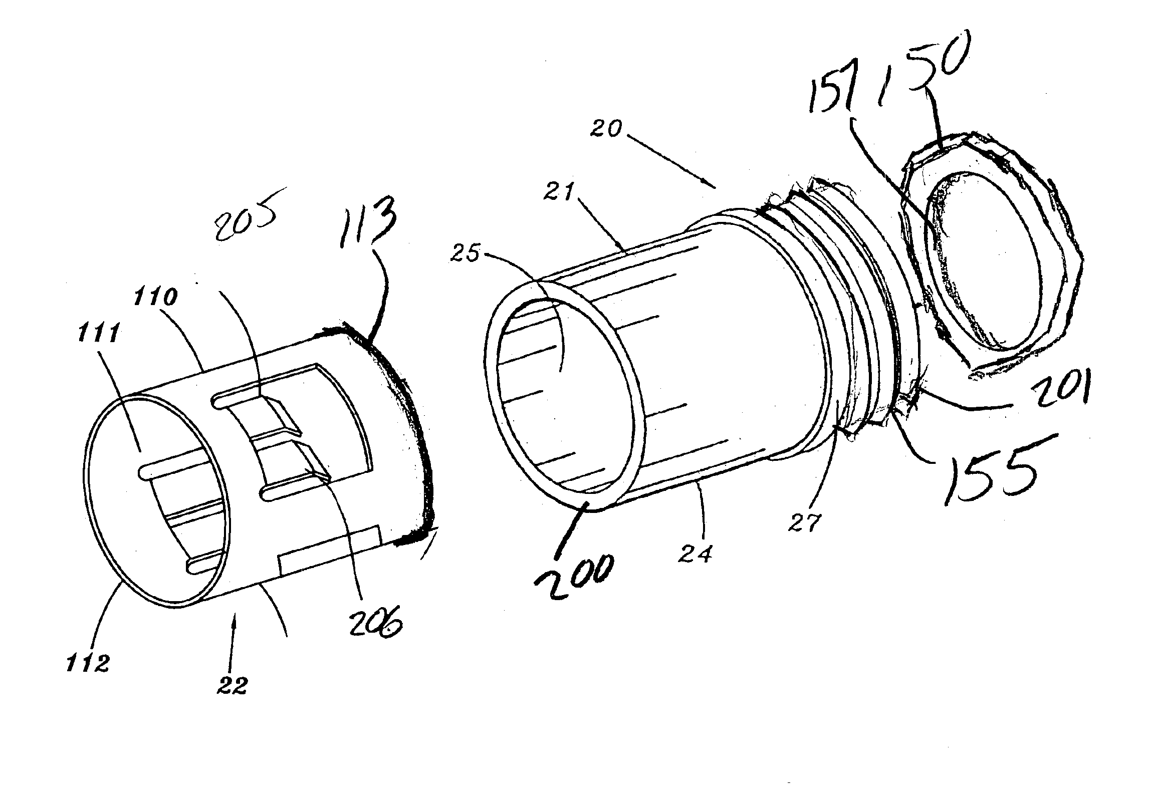
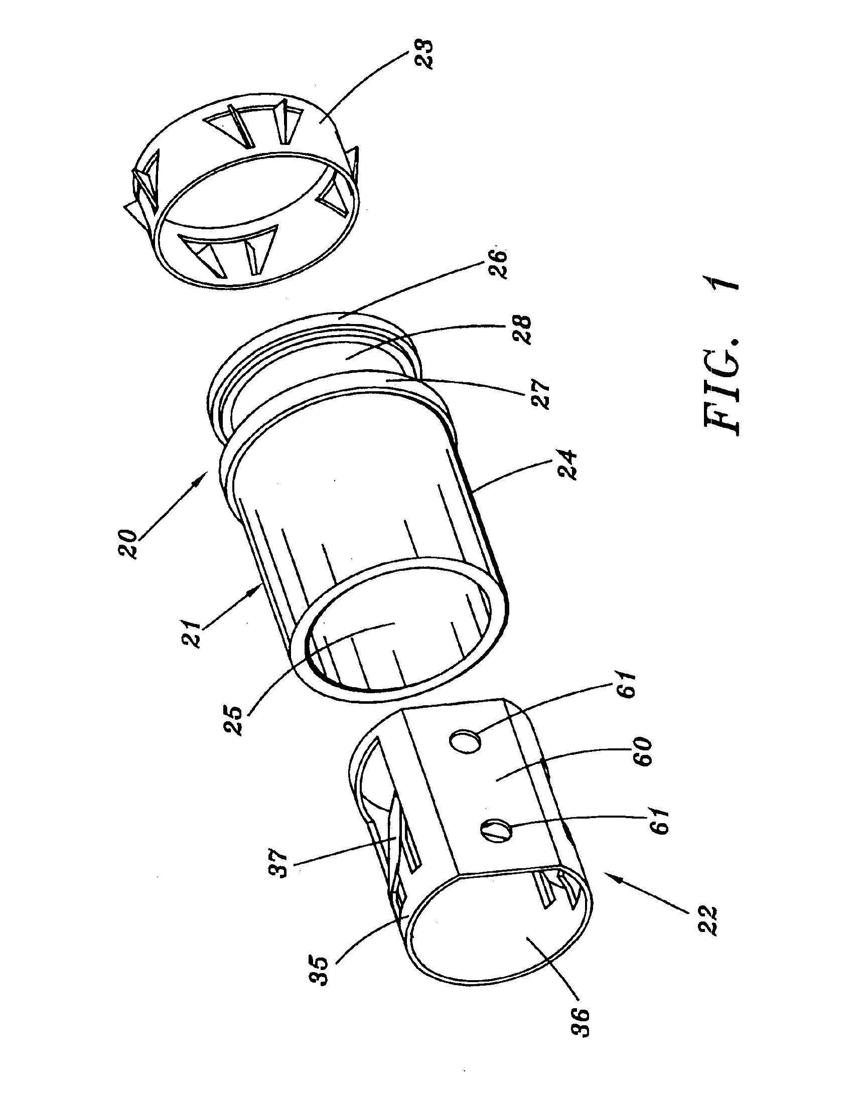
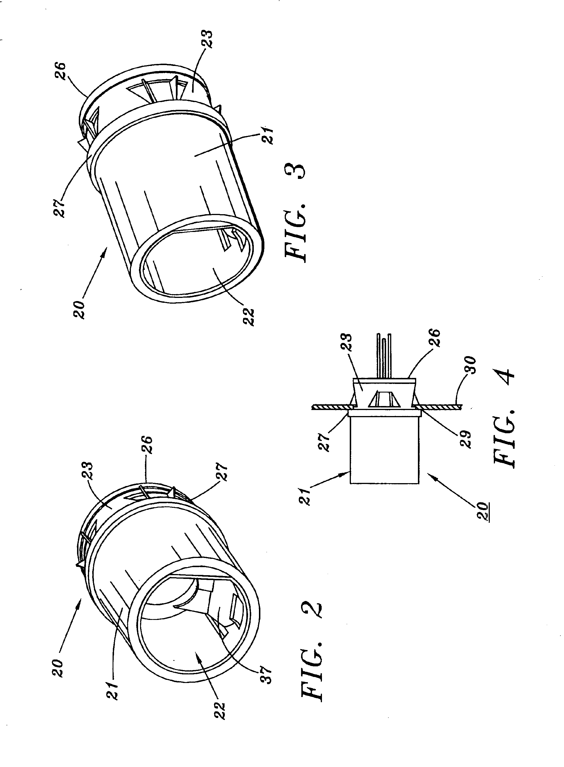
By referring to FIGS. 1-41, along with the following detailed disclosure, the construction and operation of several alternate embodiments of electrical cable connector 20 of the present inventions can best be understood. As will be evident to one having ordinary skill in this art, numerous alternate constructions may be implemented using the teaching of the present invention in addition to the embodiments shown and described herein. Consequently, it is to be understood, that all of these alternate constructions are intended to be within the scope of the present invention and the embodiments detailed herein are provided for exemplary purposes only.

As shown in FIGS. 1-4, cable connector 20 of the present invention comprises three separate and independent components, consisting of housing 21, inner sleeve member 22, and locking ring 23. In the preferred construction, housing 21 comprises a substantially hollow cylindrical shape incorporating outer surface 24, and inner surface 25. In a...


PUM


Abstract

By providing at least two integrated components, an outer housing and an inner sleeve member, with the inner sleeve member being securely mounted to the outer housing in a manner which prevents its separation from the housing, an efficient, easily manufactured and assembled cable connector is realized. In the preferred embodiment, the inner sleeve member is press fitted into the housing in order to provide the desired secure, integrated affixation of these components. Furthermore, the inner sleeve member is constructed in a generally hollow cylindrical shape with at least two arm members integrally formed therewith, each of which angularly slopes inwardly from the cylindrical wall of the sleeve member, and includes a distal end portion which is angularly disposed relative to the arm member in at least one direction and preferably in two directions.

Description

TECHNICAL FIELDThis invention relates to electrical connectors, and more particularly, to electrical connectors constructed for securing metal sheath cables to junction boxes and / or outlet boxes.BACKGROUND ARTIn the field of wiring homes and buildings, whether for new construction or for improvements or expansion, substantial development and product improvements have been made. Typically, these improvements are directed to enabling installers to securely mount any desired wiring in any desired location in the most efficient and quickest manner.In any particular installation or location, various cables must be interconnected to each other as well as connected to the primary power supply in a suitable power distributing junction box or fuse box. In each of these instances, metal sheath cables, within which the electric power carrying wires are contained, must be securely mounted to the housing of the junction box or outlet box, or connected to appropriate devices, in a protected area....

Claims


Application Information

Patent Timeline
Patent Type & Authority Patents(United States)
IPC IPC(8): H02G3/02H02G3/06H01R13/58
CPCH02G3/0691H01R13/5804Y10T16/05
Inventor KIELY, KENNETH M.
Owner BRIDGEPORT FITTINGS LLC
Why Eureka
Try Eureka