Conversion of an HDL sequential truth table to generic HDL elements

a technology of hdl elements and truth tables, applied in the field of electronic design automation, can solve the problems of generating problems for certain generic algorithms, providing no insight into the physical make-up of the circuit elements being represented, and operating on an hdl element at the truth table level may provide insufficient detail

Inactive Publication Date: 2005-03-29
SIEMENS PROD LIFECYCLE MANAGEMENT SOFTWARE INC
View PDF6 Cites 18 Cited by
  • Summary
  • Abstract
  • Description
  • Claims
  • Application Information

AI Technical Summary

Problems solved by technology

A truth table, however, generally provides no insight into the physical make-up of the circuit elements being represented.
HDL descriptions that include non-generic elements, such as technology-specifi

Method used


Image

  • Conversion of an HDL sequential truth table to generic HDL elements
  • Conversion of an HDL sequential truth table to generic HDL elements
  • Conversion of an HDL sequential truth table to generic HDL elements

Examples


first embodiment

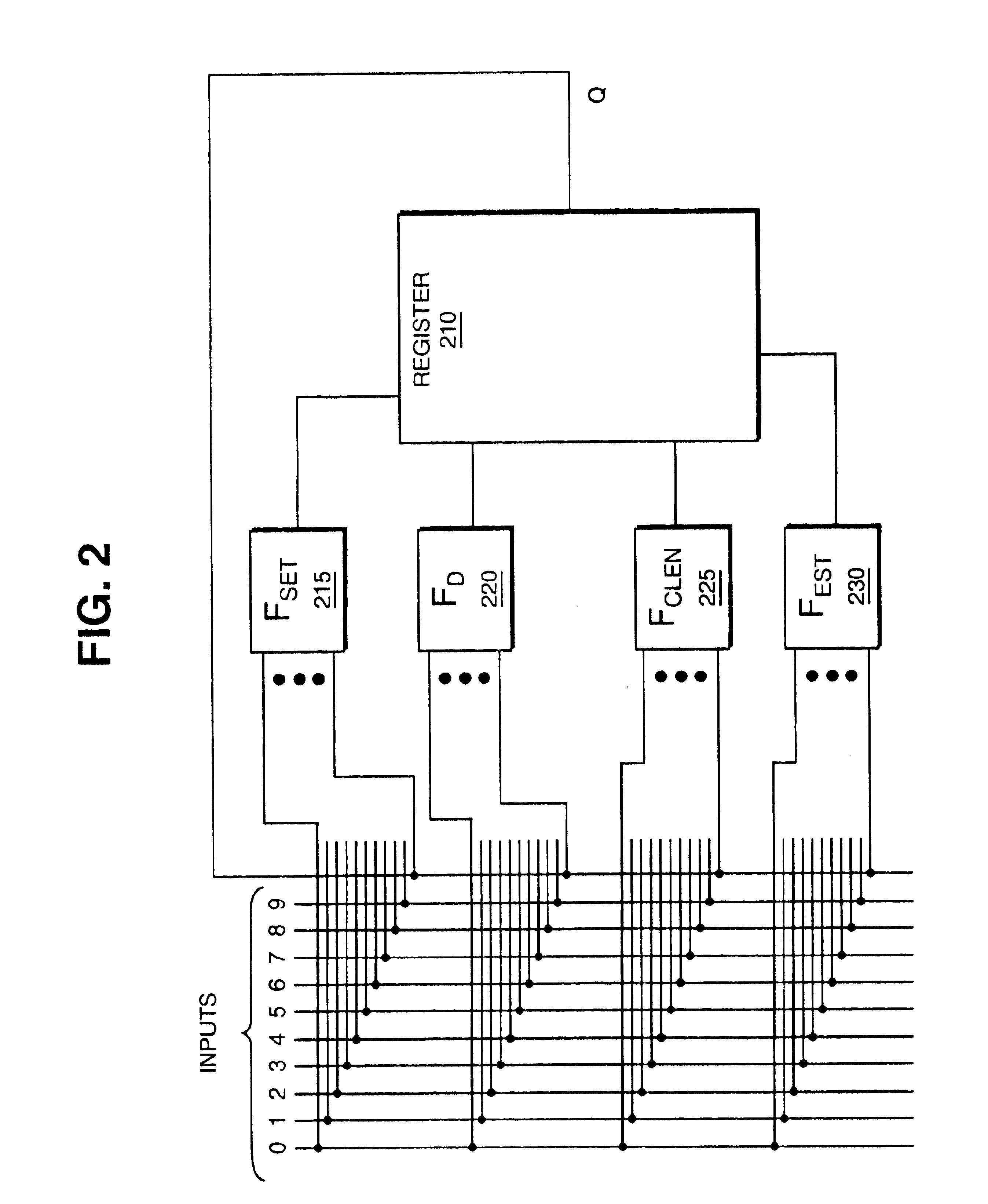
Sorting the columns is different for a level sensitive device. The enable, set, and reset functions are all level sensitive, providing more flexibility in the formation of the logic functions. Various embodiments of functions are given below. In this first embodiment, the behavior of a level sensitive UDP can be equivalently modeled using a latch and logic functions on only the set and reset inputs of the latch.Fset=L01+DC[L11]Frst=L10+DC[L00]Fclen=0Fd=0

In this next embodiment of functions, the enable and data logic functions are used to model the UDP behavior.Fset=0Frst=0Fclen=L01+DC[L11]∪L10+DC[L00]Fd=L01+DC[L11 ]

third embodiment

Below is a third embodiment for determining primitives for a level sensitive UDP.Fset=Signal identified with the method discussed belowFrst=Signal identified with the method discussed belowFtmp1=L01+DC[L11∪LUR01∪LUR11]Ftmp2=L10+DC[L00∪LUR10∪LUR00]Fclen=[Ftmp1∪Ftmp2]+DC[Fset∪Frst]Fd=Ftmp1 and using the invert of the function Fclen as Don't Care

In this last embodiment, the set and reset inputs of the latch are connected directly to individual respective inputs. A set signal that is active high is identified directly from reachable states in the conversion matrix by finding a signal for which there is no state where the signal is one and the next output state Q+ is zero. That is, there can be no state in which set is active and the next output state is not set. A similar search can be done to identify a reset signal. The remaining functions are evaluated in much the same way as those described above for the edge triggered UDP.

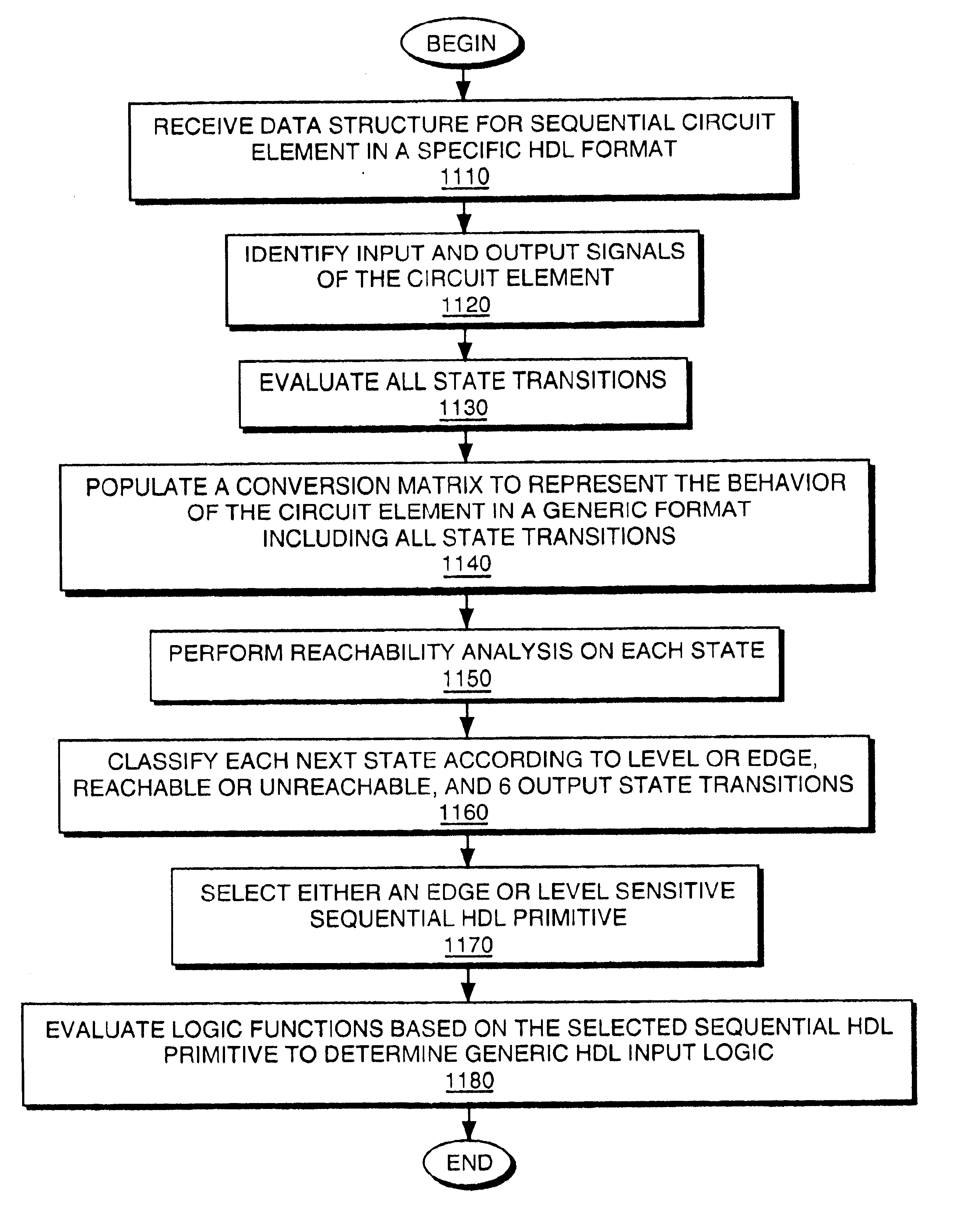
FIG. 11 demonstrates one embodiment of the present invention...


PUM


Abstract

An HDL conversion process receives a data structure representing the behavior of a circuit element. The circuit element is sequential and the data structure is defined in a hardware description language (HDL) using a specific format. The conversion process generates a conversion matrix from the data structure. The conversion matrix represents the behavior of the circuit element in a generic format. The conversion process then determines a generic HDL register and a plurality of generic HDL input logic for the generic HDL register to replicate the behavior represented by the data structure based on the conversion matrix.

Description

FIELD OF THE INVENTIONThe present invention pertains to the field of electronic design automation. More particularly, this invention relates to converting hardware description language (HDL) sequential truth tables to generic HDL elements.BACKGROUNDElectronic design automation (EDA) includes a wide variety of tools used to create integrated circuits. Hardware description languages (HDLs) are one such tool. Verilog and Very High Speed Integrated Circuit (VHSIC) Hardware Description Language (VHDL) are two common examples of HDLs. HDLs often resemble programming languages and can be used to describe integrated circuits in a written format. A written HDL description can be used by various other EDA tools to simulate an integrated circuit, synthesize a different kind of representation of an integrated circuit, fabricate a physical integrated circuit, check the equivalency of two integrated circuits, modify an integrated circuit design for various purposes such as testability, and the li...

Claims


Application Information

Patent Timeline
IPC IPC(8): G06F17/50
CPCG06F17/5045G06F30/30
Inventor COLLIN, JEROMEJACOBY, REILY M.PARDO, ABELARDO
Owner SIEMENS PROD LIFECYCLE MANAGEMENT SOFTWARE INC
Why Eureka
Try Eureka