
Connecting device for weapon accessory

a technology of connecting device and weapon, which is applied in the field of connecting device for weapon accessories, can solve the problems of increased manufacturing and material costs, difficult connection, and consuming to assemble or disassemble the connecting device, and achieve the effect of reliable securement of an accessory to the weapon

Inactive Publication Date: 2005-04-05
QUARTON
View PDF24 Cites 54 Cited by
  • Summary
  • Abstract
  • Description
  • Claims
  • Application Information

AI Technical Summary

Benefits of technology

It is one objective of the present invention to provide a connecting device for a weapon accessory that can reliably secure an accessory to the weapon.
It is another objective of the present invention to provide a connecting device for a weapon accessory that can be quickly and conveniently secured to and removed from the weapon.

Problems solved by technology

(a) The construction of certain conventional connecting devices is complex, so it can be difficult and time-consuming to assemble or disassemble the connecting device, and to secure the connecting device to the weapon. The complex construction also results in increased manufacturing and material costs.
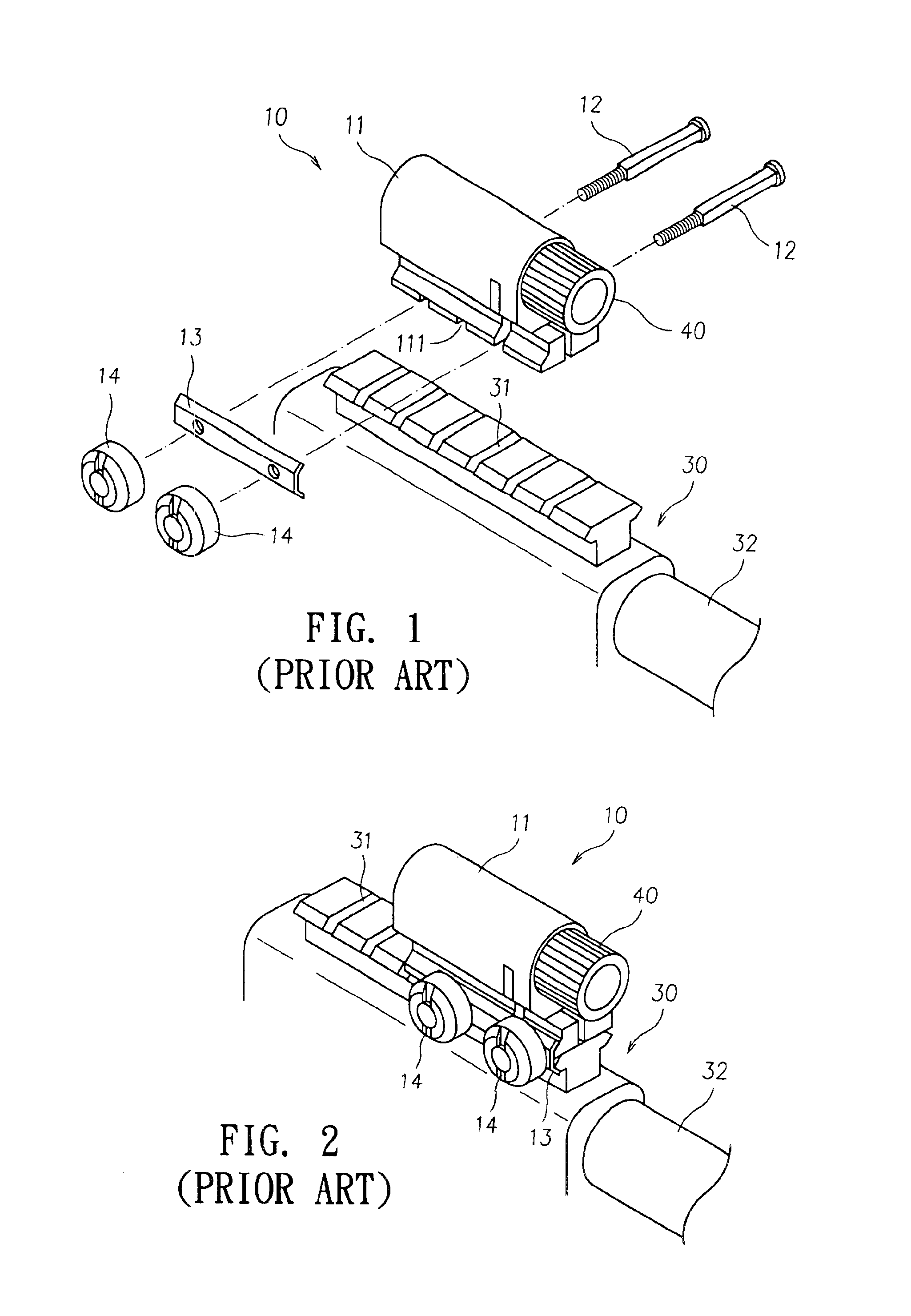
(b) Close manufacturing tolerances may be required. In the connecting device of FIGS. 1 and 2, the connection of the main body 11 and the inner diameter of the selected groove 31 by the square bolt 12 requires precise tolerances. If the inner diameter of the groove 31 varies, or the size of the bolt 12 varies, the connection can be difficult to accomplish. For example, the main body 11 may not be securely attached to the groove 31, or it may be difficult to screw the square bolt 12 into the groove 31.

Method used


Image

  • Connecting device for weapon accessory
  • Connecting device for weapon accessory
  • Connecting device for weapon accessory

Examples


Embodiment Construction

The following detailed description is of the best presently contemplated modes of carrying out the invention. This description is not to be taken in a limiting sense, but is made merely for the purpose of illustrating general principles of embodiments of the invention. The scope of the invention is best defined by the appended claims.

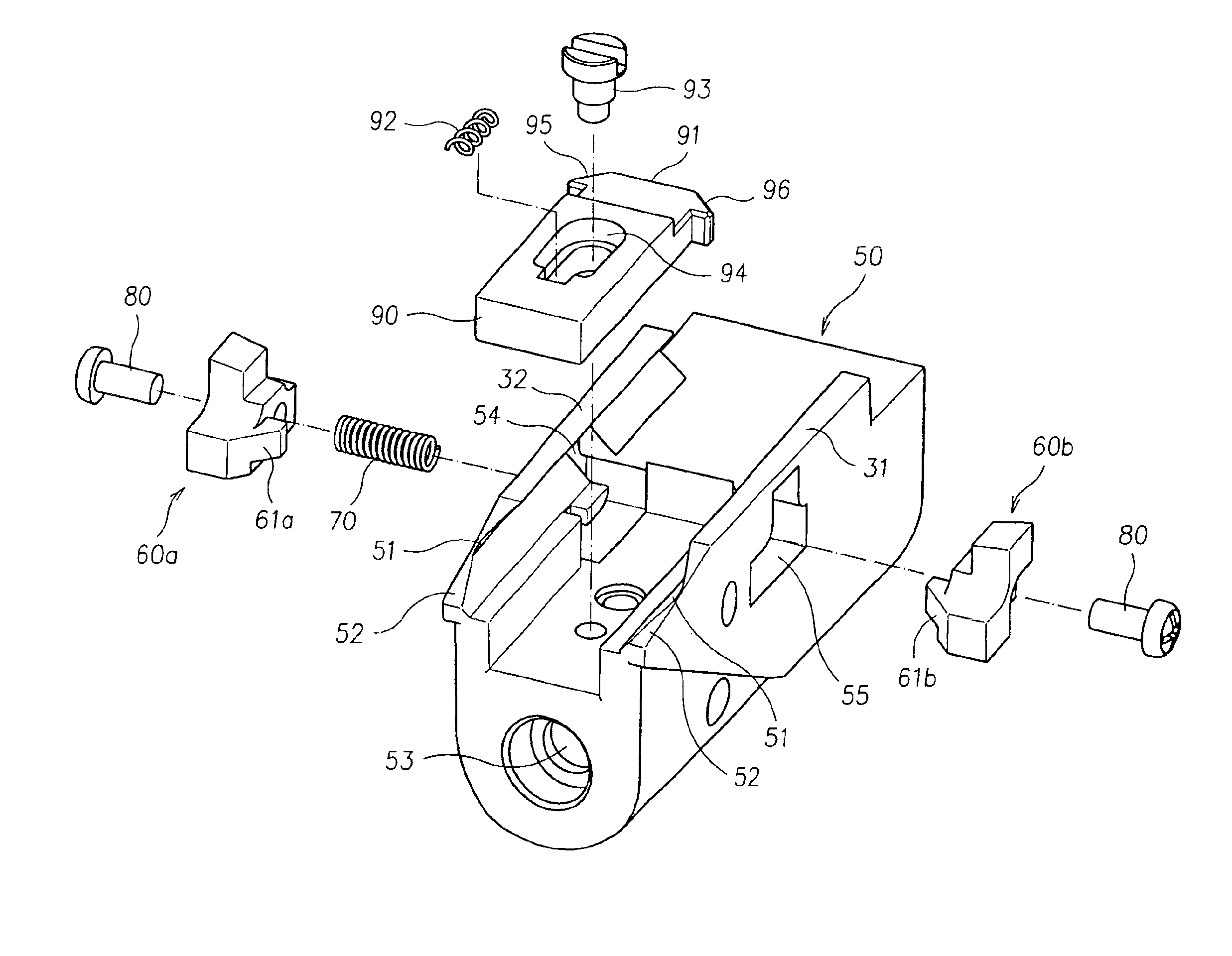
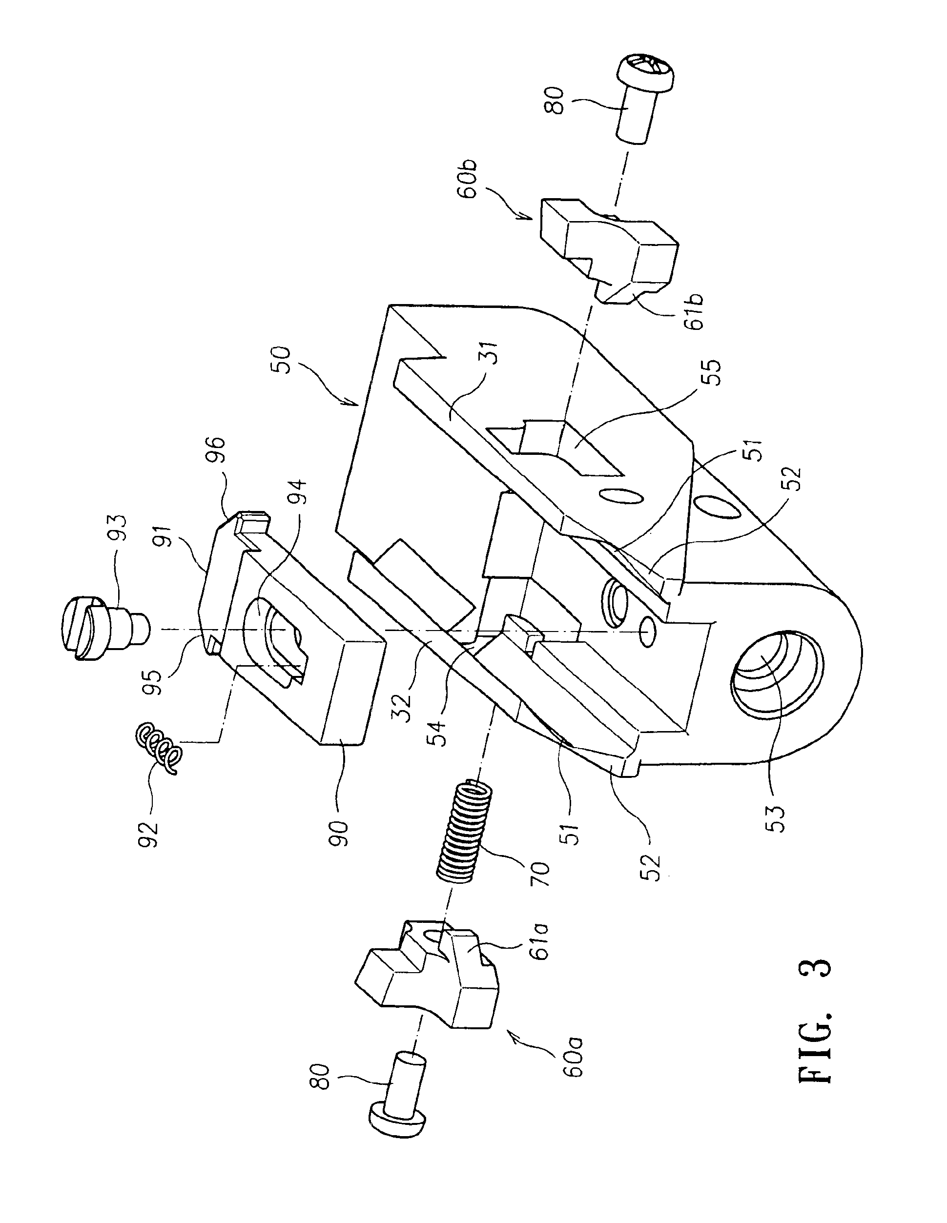
FIGS. 3 and 4 illustrate one embodiment of a connecting device according to the present invention. The connecting device has a seat 50, two sliding blocks 60a and 60b, and a control mechanism.

The seat 50 has a left side wall 31 and a right side wall 32. Sliding racks 51 are provided adjacent the top of the side walls 31, 32. A front surface 52 is provided at the front of the side walls 31, 32. Each side wall 31 and 32 has a corresponding opening 55 and 54, respectively, that are aligned with each other.

Each sliding block 60a and 60b is fitted through a corresponding opening 54 and 55, respectively, of the corresponding side wall 32 and 31, respectively....


PUM


Abstract

A connecting device for a weapon accessory has a seat having a sliding rack that removably connects the longitudinal groove of a weapon, and one or more gripping blocks disposed adjacent corresponding side walls of the seat. The gripping block assumes a first position where the gripping block extends inwardly towards the sliding rack to engage a selected transverse groove of the weapon, and a second position where the gripping block extends outwardly away from the respective side wall of the seat to release the longitudinal groove of the weapon. The connecting device also includes a control mechanism operatively coupled to the gripping block. The control mechanism assumes a normal position with the control mechanism controlling the gripping block to maintain the gripping block in the first position, and actuation of the control mechanism causes the gripping block to assume the second position.

Description

BACKGROUND OF THE INVENTION1. Field of the InventionThe invention relates to weapon accessories, and in particular, to a connecting device for connecting an accessory to a weapon (such as a pistol).2. Description of the Prior ArtWeapons, such as pistols, shotguns and rifles, among others, are often used with accessories (such as aiming devices) that assist the user in the use of the weapon. These accessories are removably secured to the weapon by a connecting device. There have been many connecting devices that have been provided in the prior arts.FIGS. 1 and 2 illustrate one conventional connecting device for a weapon accessory. The conventional connecting device comprises a main body 11 for receiving a weapon accessory 40, which is typically a laser aiming device. The conventional connecting device has a groove 111 on the bottom side of the main body 11 that matches one of a plurality of grooves 31 on the corresponding side of the weapon 30. The main body 11 is secured within the ...

Claims


Application Information

Patent Timeline
IPC IPC(8): F41G1/387F41G1/00
CPCF41G11/003
Inventor CHEN, TONY K. T.CHIU, MING-CHUNGLIOU, WUN-CHUNWU, CHAO-HUNG
Owner QUARTON
Learn More