Humidifier with a heating disc

a technology of humidifier and heating disc, which is applied in the direction of heating types, lighting and heating apparatus, and separation processes, etc., can solve the problems of user not knowing whether the device is working, process may take time, and danger to people who come into contact with steam

Inactive Publication Date: 2005-04-05
HELEN OF TROY LIMITED
View PDF13 Cites 77 Cited by
  • Summary
  • Abstract
  • Description
  • Claims
  • Application Information

AI Technical Summary

Benefits of technology

In another embodiment, the method may include the steps of collecting and returning unevaporated liquid to the reservoir. At least a portion of the disc may be connected to the base adjacent to where the disc receives the stream of liquid. The method may include the step of connecting an entire edge of the disc to the base. The method may include the step of providing a liquid storage tank for delivering liquid to the reservoir. The tank may be removably connected to the reservoir. The surface of the disc may be a top surface. The disc may be angled away from a plane from a portion of the disc receiving the stream of liquid. The plane may be horizontal and the disc may be angled below the horizontal plane. The liquid received on the surface of the disc may have a depth and the depth may be at least less than about 8 mm. At least a portion of the stream of liquid may be provided as a mist, a thin film or a controlled stream. The method may include the steps of directing the evaporated liquid through a nozzle provided above the disc to a venturi, and releasing the evaporated liquid from the venturi out of the humidifier.

Problems solved by technology

As the steam is hot, it may pose a danger to people who come into contact with the steam, or who accidentally overturn the container of hot water.
This process may take time and the user may not know whether the device is working, while they wait for steam to be generated.
As the water is not boiled, ultrasonic humidifiers are susceptible to the growth of microorganisms, which may be subsequently carried by the air stream into the room being humidified.
As the water is not boiled, this method can also lead to the growth of microorganisms, which may be subsequently carried by the air stream into the room being humidified.
Because boiling must occur, this method may take time and the user may not know whether the device is working.
This type of humidifier may also be complex and expensive.

Method used


Image

  • Humidifier with a heating disc
  • Humidifier with a heating disc
  • Humidifier with a heating disc

Examples


Embodiment Construction

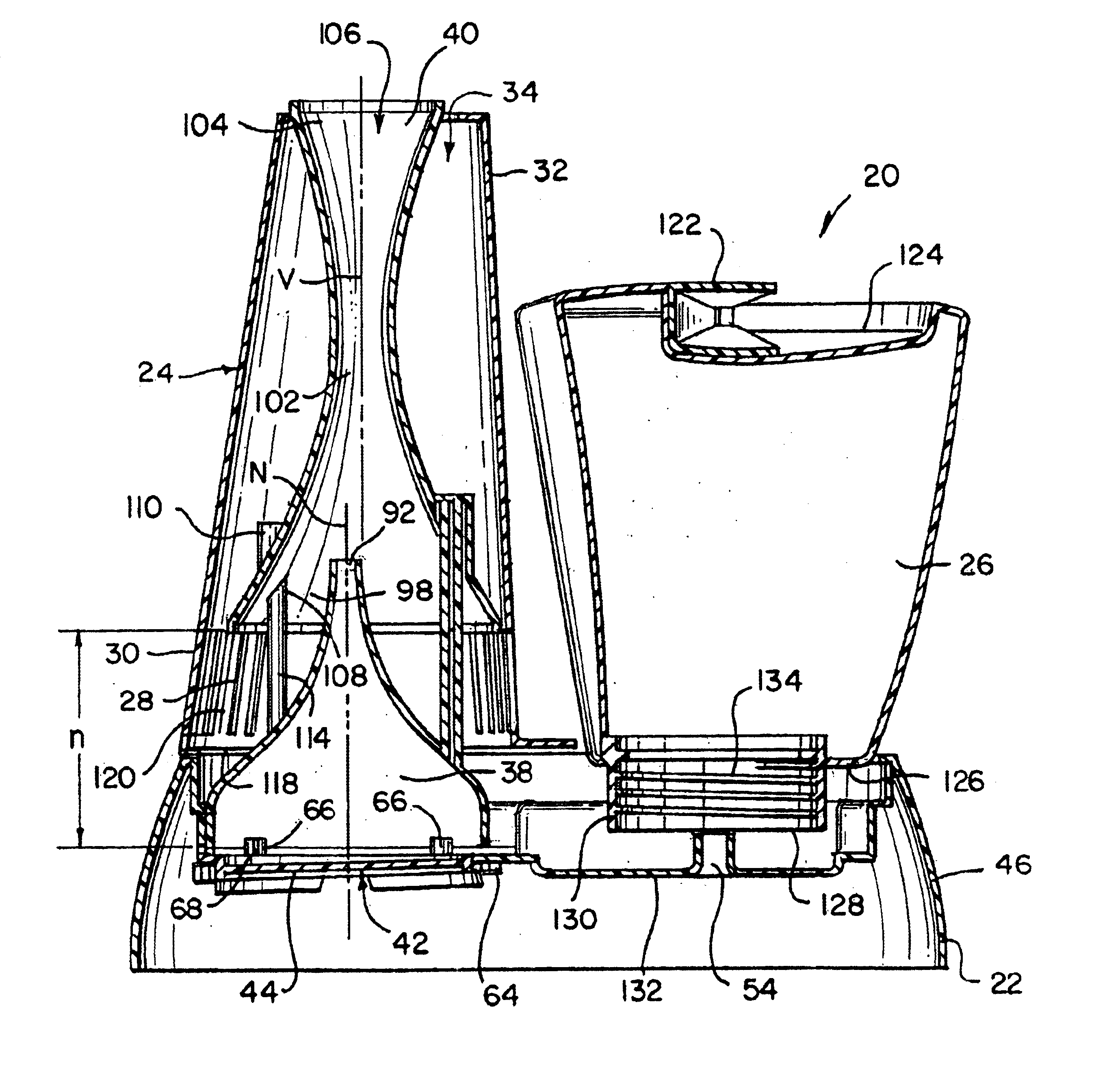
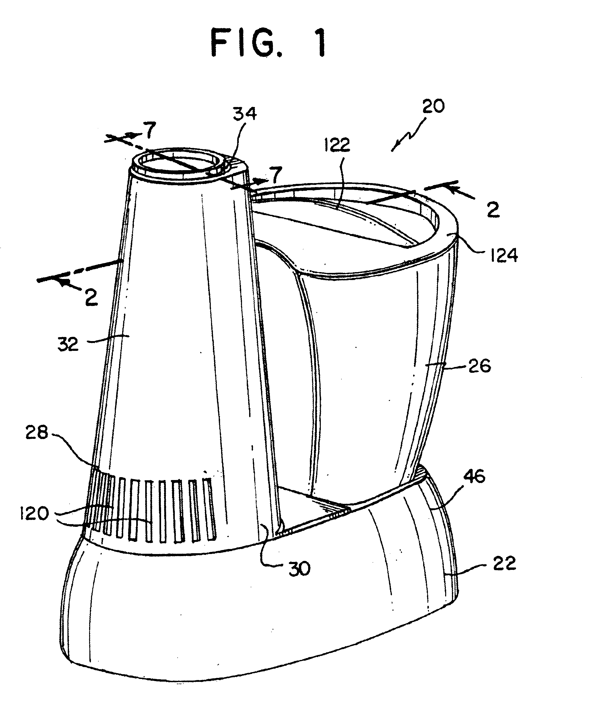
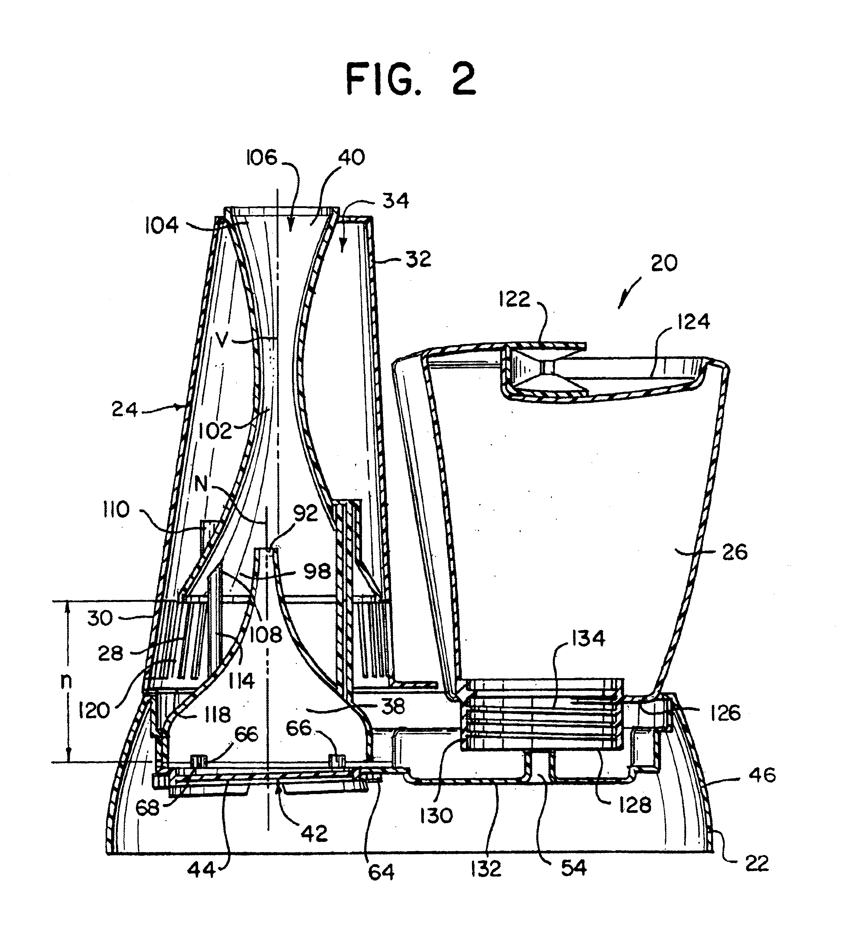
As discussed above, illustrative embodiments in accordance with the invention provide a humidifier with a humidification unit that provides steam without having to boil a large quantity of liquid, thus resulting in a shorter time to produce steam. The humidification unit is provided on a base defining a liquid reservoir. The humidification unit features a heatable disc that receives a stream of liquid from the reservoir. At least a part of the stream of liquid on the disc evaporates into the air to humidify the environment. The heatable disc and stream of liquid may be provided in numerous different embodiments, a few of which will be discussed herein.

Referring now to FIGS. 1-2 and 7, a humidifier 20 according to the present invention illustrated. The humidifier 20 includes a base 22. Mounted in juxtaposed positions on the base 22 are a humidification unit 24 and a removable liquid storage tank 26. The humidifier 20 has an air inlet 28 formed in a lower portion 30 of a housing 32 of...


PUM

PropertyMeasurementUnit
angleaaaaaaaaaa
angleaaaaaaaaaa
depthaaaaaaaaaa

Abstract

A humidifier includes a base defining a reservoir for retaining liquid, a humidification device for inducing dispersion of liquid withdrawn from the reservoir into the environment and a liquid storage tank having an outlet for feeding liquid into the reservoir. The humidification device includes a heated disc for evaporating a stream of liquid delivered from the reservoir to the heated disc by a delivery mechanism. The delivery mechanism may deliver the stream of liquid as a mist, a thin film or a controlled stream of liquid onto the disc.

Description

FIELD OF THE INVENTIONThis invention relates to humidifiers, and more specifically, to a humidifier with an improved humidification device including a heatable disc.BACKGROUND OF THE INVENTIONVarious types of humidifiers are used to provide moisture to indoor air. Included among such humidifiers are steam humidifiers, ultrasonic humidifiers, porous medium humidifiers and evaporative humidifiers. Many humidifiers employ a removable water storage tank, which can be removed for filling. Typically, a bottom wall of the storage tank is provided with a valve assembly that regulates water flow to maintain a desired water level in a reservoir supplying a humidification device.Steam humidifiers include a water storage tank and an electric heating element submerged in water to generate steam. Safety devices are provided for switching off the current as soon as the water level drops below the heating element. A flow of hot steam is blown directly into the room to be humidified. As the steam is...

Claims


Application Information

Patent Timeline
Patent Type & Authority Patents(United States)
IPC IPC(8): F24F6/02F24F6/10
CPCF24F6/10Y10S261/65
Inventor BIRDSELL, WALTER G.FEER, DAVIDMONTAGUE, JR., WILLIAM J.
Owner HELEN OF TROY LIMITED
Why Eureka
Try Eureka