Integral tip seal in a fan-shroud structure

a fan-shroud and integrated technology, applied in the direction of valve construction, marine propulsion, liquid fuel engines, etc., can solve the problems of improper seal design, ribs that do not effectively seal air leakage through the tip gap, and difficulty in manufacturing, so as to reduce noise and increase fan efficiency.

Inactive Publication Date: 2005-04-05
BROSE FAHRZEUGTEILE GMBH & CO KG HALLSTADT (DE)
View PDF17 Cites 33 Cited by
  • Summary
  • Abstract
  • Description
  • Claims
  • Application Information

AI Technical Summary

Benefits of technology

is to provide an effective means of reducing noise and increasing the fan efficiency by minimizing air leakage and its swirling component between banded fan blade tips and the shroud.

Problems solved by technology

A disadvantage of the labyrinth seal is that this seal is difficult to manufacture and that often the manufacturing tolerances limit the proper design of the seal.
However, the ribs do not seal air leakage through the tip gap effectively.

Method used


Image

  • Integral tip seal in a fan-shroud structure
  • Integral tip seal in a fan-shroud structure
  • Integral tip seal in a fan-shroud structure

Examples


Embodiment Construction

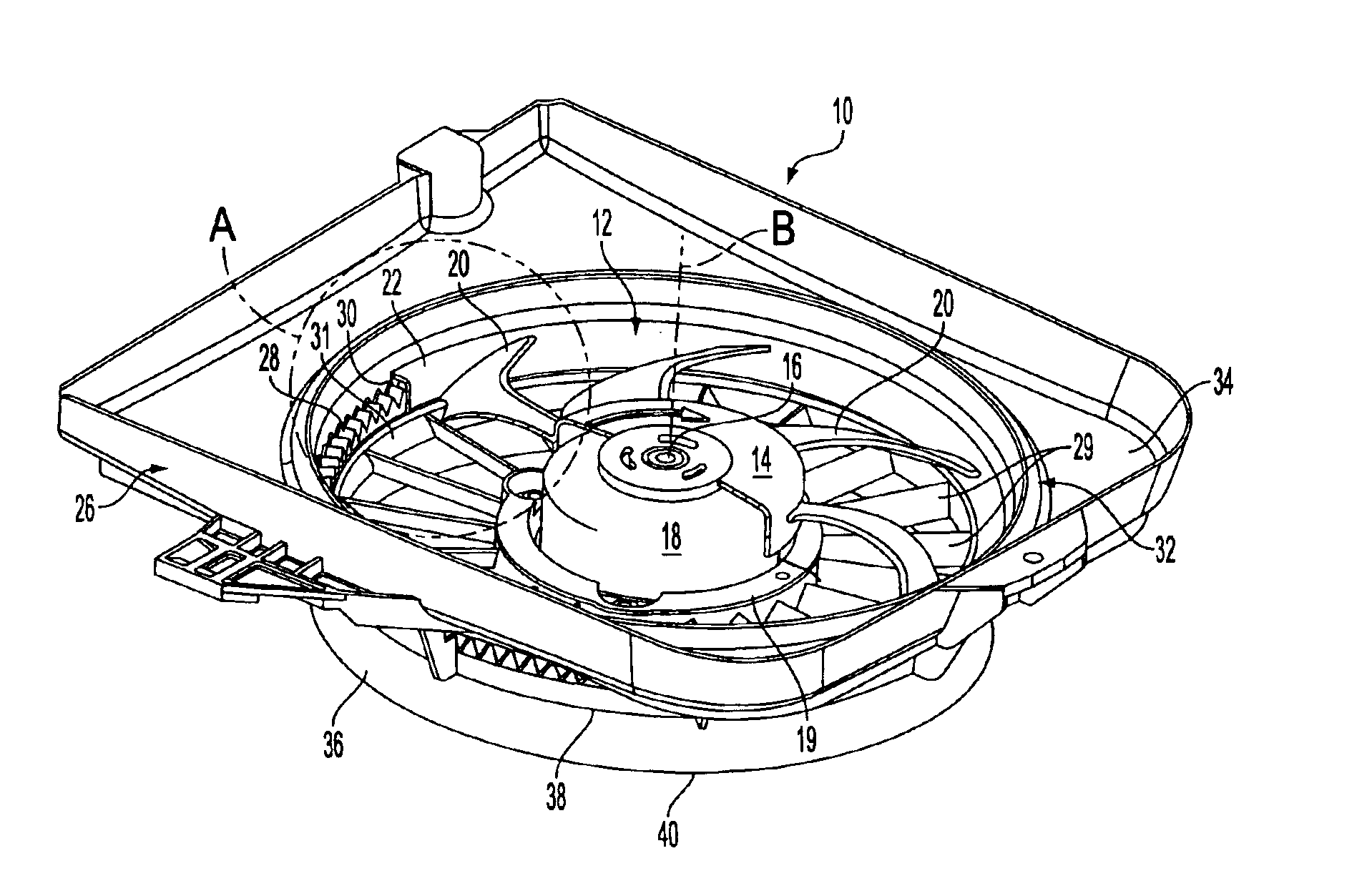
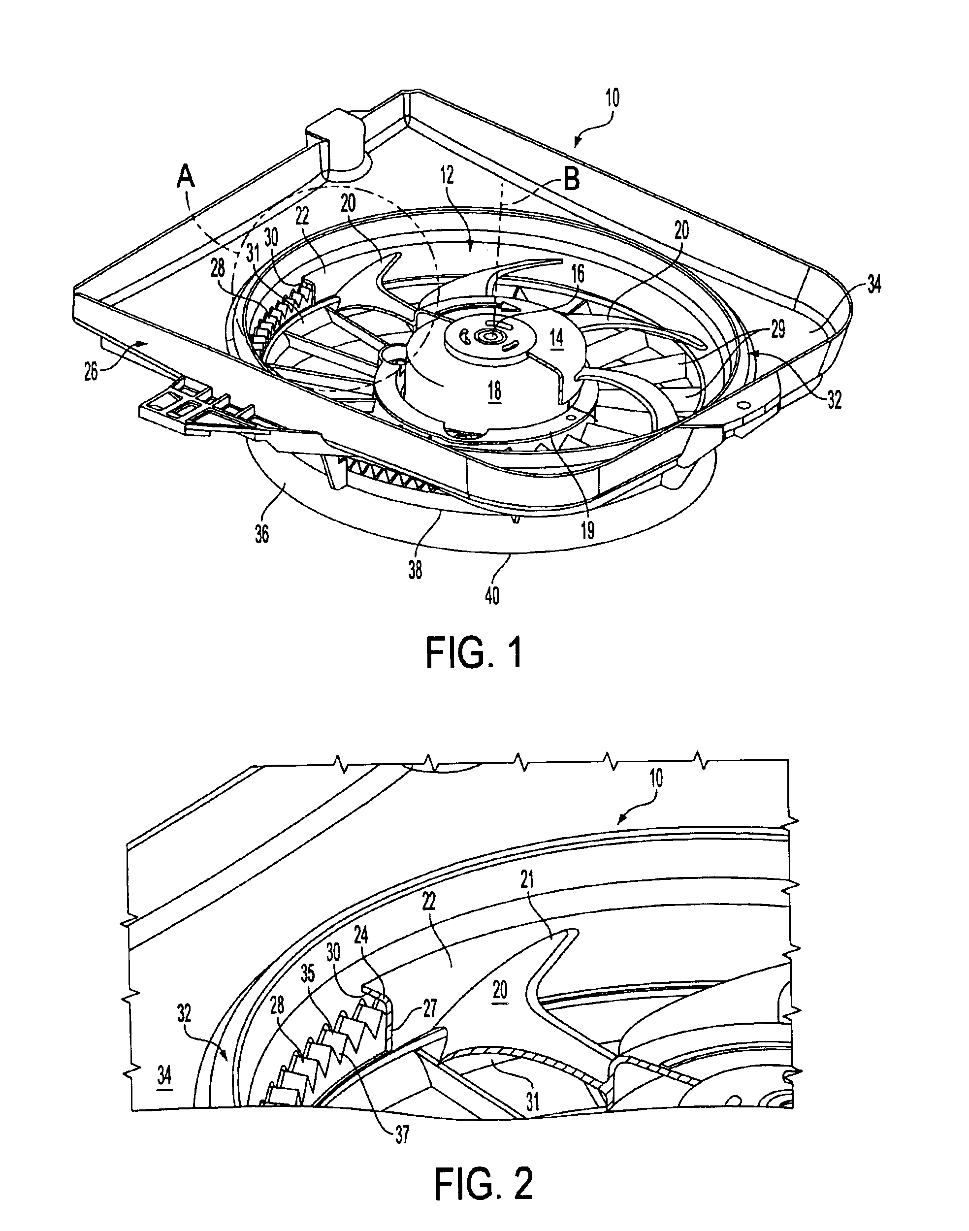
A fan-shroud structure, generally indicated at 10, is shown in FIG. 1 in accordance with the principles of the invention. The fan-shroud structure 10 includes a fan, generally indicated at 12, having a hub 14 coupled with a shaft 16 of a motor 18 for rotation of the fan 12 about axis B. The fan includes a plurality of blades 20. Each blade 20 is coupled to the hub 14 at one end thereof and the tip 21 of each blade 20 is coupled to an annular band 22. As best shown in FIG. 2, the band 22 is preferably L-shaped, having a radially extending portion 24 and an axially extending portion 27. The motor 18 is mounted to a shroud, generally indicated at 26. The shroud 26 includes support ribs 29 that extend from body 34 of the shroud 26 to a motor mount portion 19 of the shroud. The ribs 29 are generally adjacent to the blades 20 of the fan 12.

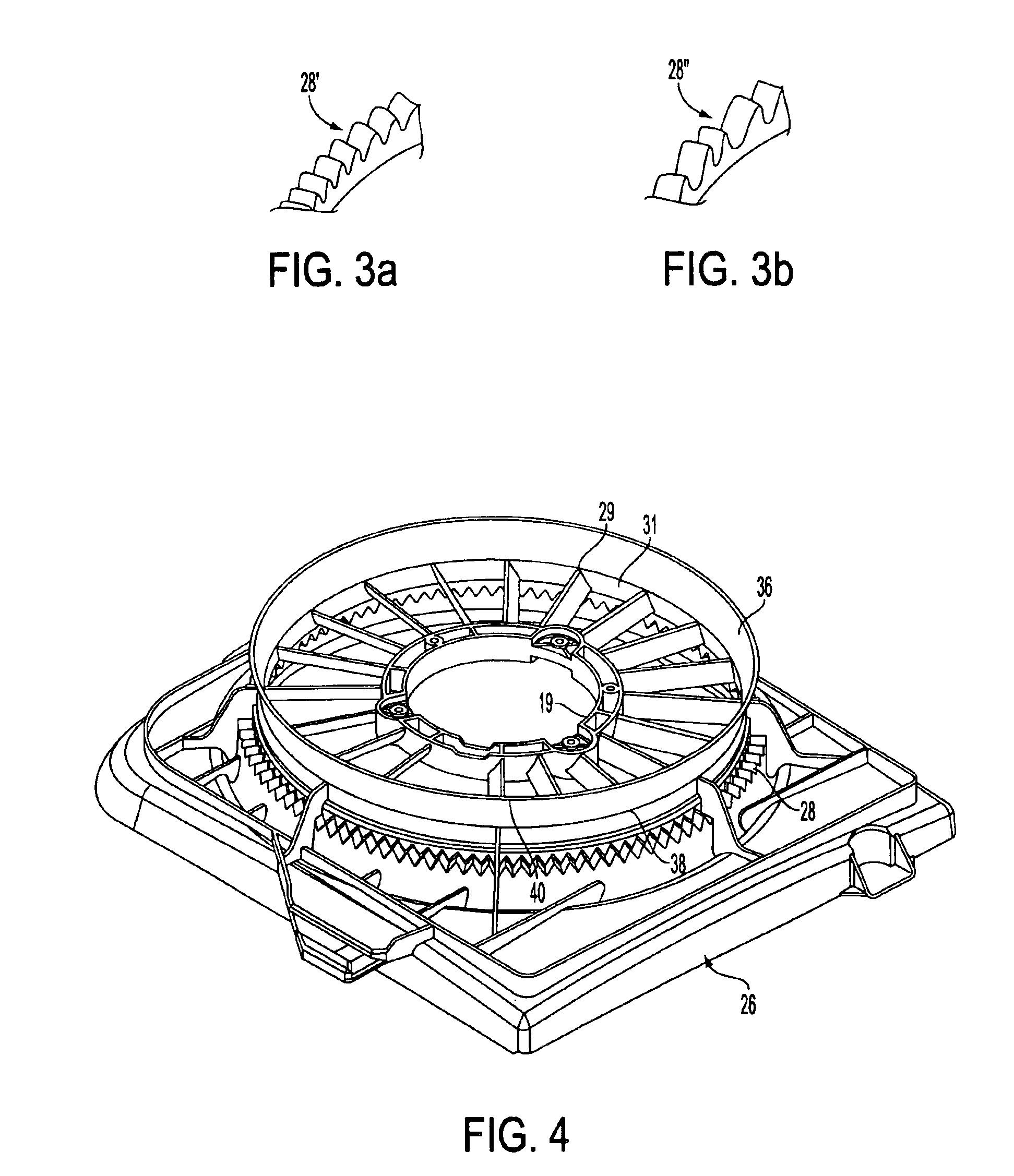
In accordance with the invention, the shroud 26 includes an improved labyrinth seal 28 having a corrugated profile. The seal 28 is preferably molded as...


PUM


Abstract

A fan-shroud structure 10 includes a fan 12 mounted for rotation about an axis B. The fan has a plurality of blades 20 with tips of the blades being coupled to an annular band 22. A shroud 26, including an annular labyrinth seal 28, is disposed generally adjacent to the annular band thereby defining a gap 30 between the annular band and the seal. The seal has a corrugated profile and is constructed and arranged to provide resistance to air flow as air swirls and flows back into the gap and to minimize air leakage across the gap.

Description

FIELD OF THE INVENTIONThe invention relates to fan efficiency increase and noise reduction of fans for engine cooling applications. The primary object of the invention is to provide an effective means of reducing noise and increasing the fan efficiency by minimizing air leakage and its swirling component between banded fan blade tips and the shroud.BACKGROUND OF THE INVENTIONConventionally, in axial flow fans, tip seals of a labyrinth type have been used to reduce tip air leakage or the flow of air in a gap (on the order of 5 mm) between the shroud and rotor (fan) in an engine cooling fan assembly. Ribs have also been used in an effort to reduce this air leakage. A disadvantage of the labyrinth seal is that this seal is difficult to manufacture and that often the manufacturing tolerances limit the proper design of the seal. Ribs in the tip region only prevent the swirling component of flow from causing turbulence by reentering the fan. However, the ribs do not seal air leakage throu...

Claims


Application Information

Patent Timeline
Patent Type & Authority Patents(United States)
IPC IPC(8): F04D29/08F04D29/16
CPCF04D29/164F04D29/326
Inventor NADEAU, SYLVAIN
Owner BROSE FAHRZEUGTEILE GMBH & CO KG HALLSTADT (DE)
Why Eureka
Try Eureka