
Electrical connector with circuit board module

a technology of circuit board module and electrical connector, which is applied in the direction of cross-talk/noise/interference reduction, coupling device connection, and coupling protective earth/shield arrangement, etc. it can solve the problem of unreliability of the connector, the increase of the number of signals in the limited space of the connector, and the problem of electromagnetic inference (emi) and the crosstalk become serious problems, etc. problems, to achieve the effect of enhancing electrical performance, simplifying configuration

Inactive Publication Date: 2005-04-05
HON HAI PRECISION IND CO LTD
View PDF7 Cites 79 Cited by
  • Summary
  • Abstract
  • Description
  • Claims
  • Application Information

AI Technical Summary

Benefits of technology

The technical effect of this patent is to create an electricity connector that has better insulation and can handle more power than previous versions. This will be done while keeping the design easy to use.

Problems solved by technology

High density electrical connectors with conductive elements arranged in a matrix pattern are needed to create many signal transmitting paths between electronic devices. These connections face issues such as electromagnetic interference and cross talk due to their close proximity and fast operation rates. Existing solutions involve complex components or difficult alignment processes. An improvement is necessary to address these challenges while maintaining efficient signal transfer at high densities.

Method used


Image

  • Electrical connector with circuit board module
  • Electrical connector with circuit board module
  • Electrical connector with circuit board module

Examples


Embodiment Construction

Reference will now be made in detail to the preferred embodiment of the present invention.

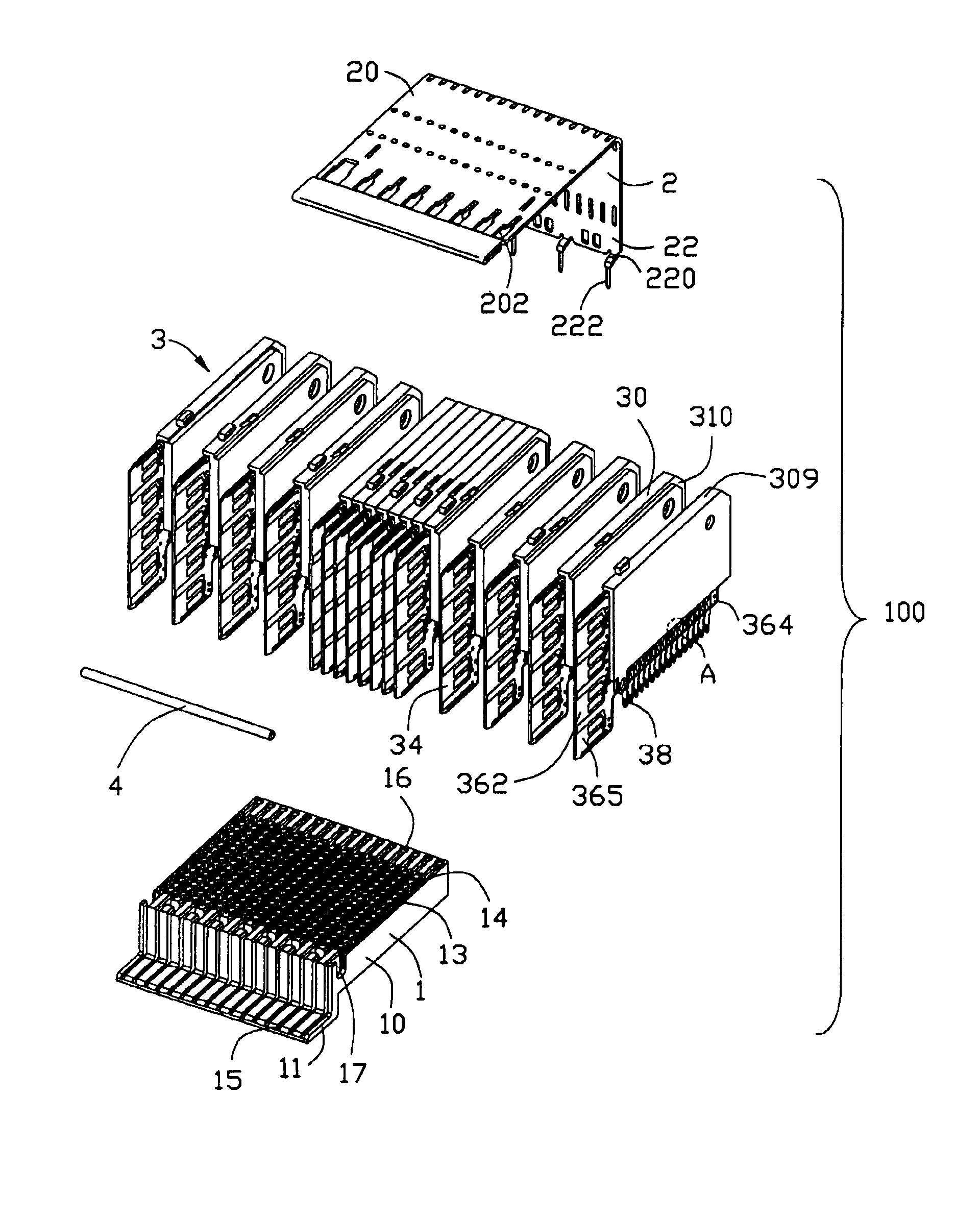
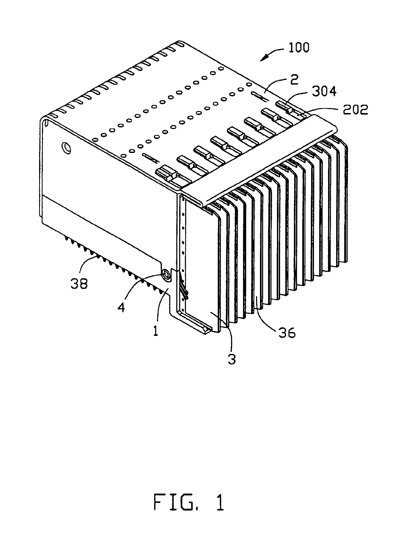
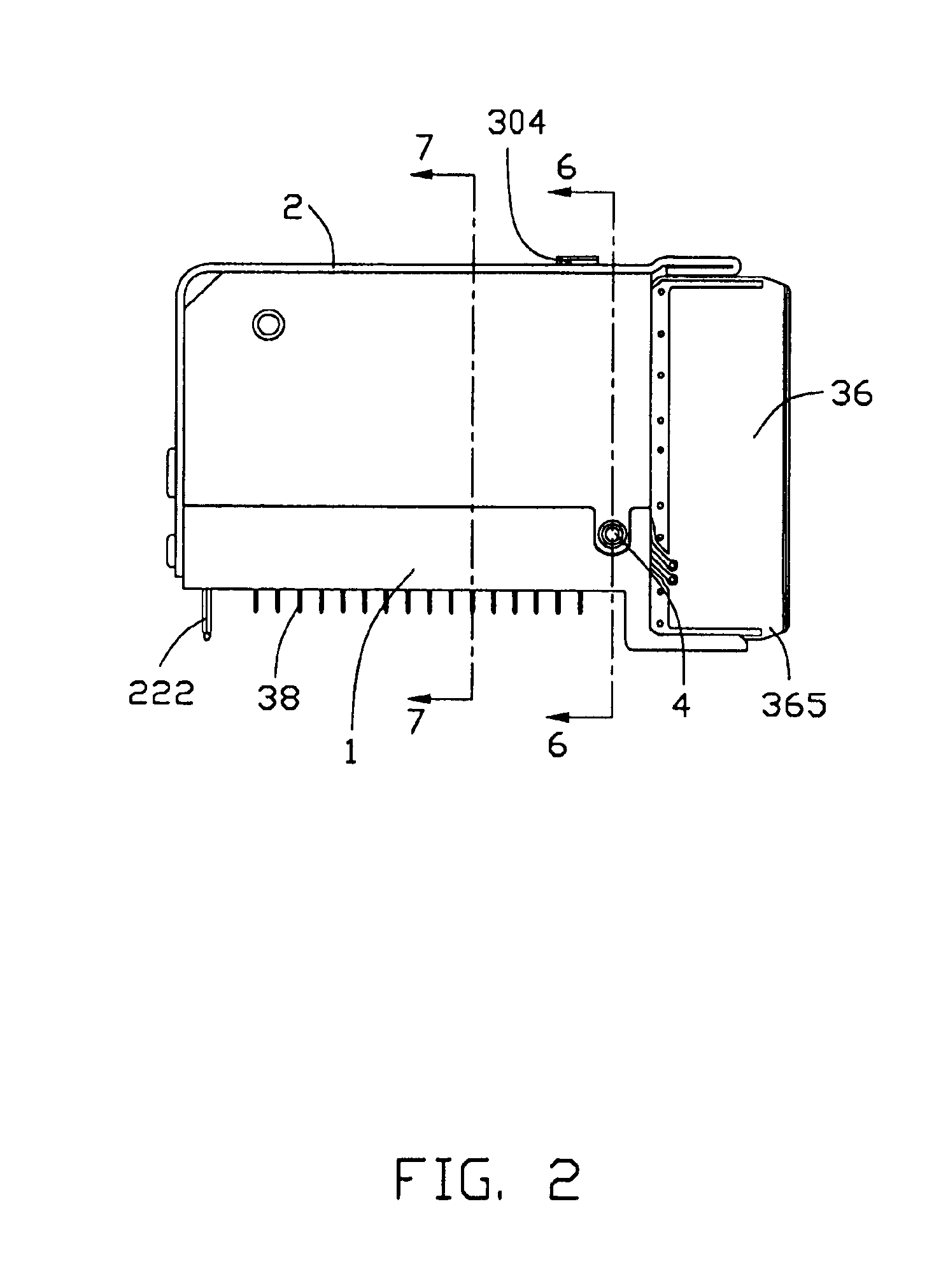
Referring to FIGS. 1, 2 and 3, an electrical connector 100 in accordance with the present invention comprises a unitary insulating housing 1, a shield member 2, a plurality of individual circuit board modules 3 received in the housing 1, and an alignment pin 4 inserting through the circuit board modules 3. The shield member 2 substantially encloses the housing 1 and the circuit board modules 3 for electromagnetic interference (EMI) protection.

The housing 1 includes a rectangular body 10 and a front tongue 11 extending forwardly from a lower portion of a front end of the body 10. The body 10 defines a plurality of parallel slots 13 extending along a longitudinal direction of the housing 1, and plural rows of passageways 14 communicating with corresponding slots 13 and penetrating through a bottom thereof. The tongue 11 defines a plurality of grooves 15 aligned with corresponding slots 13. The ho...


PUM


Abstract

An electrical connector (100) includes a unitary insulative housing (1) defining a number of parallel slots (13), a number of parallelly arranged circuit board modules (3) and a shield member (2) attached to the housing. The circuit board modules are retained by and between the shield member and the housing. Each circuit board module includes a dielectric spacer (30), a circuit board (36) attached to the dielectric spacer and received in a corresponding slot of the housing, and a row of press-fit contacts (38) mechanically and electrically connecting with the circuit board and disposed in the corresponding slot.

Description


Claims


Application Information

Patent Timeline
Owner HON HAI PRECISION IND CO LTD
Features
  • Generate Ideas
  • Intellectual Property
  • Life Sciences
  • Materials
  • Tech Scout
  • Unparalleled Data Quality
  • Higher Quality Content
  • 60% Fewer Hallucinations
Learn More