
Continuous steelmaking process

a steelmaking process and continuous technology, applied in the field of steelmaking, can solve the problems of high fluidity and high reactivity of slag according to this composition, no complete satisfactory results, and excessive wear of furnace refractory, so as to achieve low refractory wear, high melting slag composition, and high melting

Inactive Publication Date: 2005-04-05
HATCH LTD
View PDF10 Cites 5 Cited by
  • Summary
  • Abstract
  • Description
  • Claims
  • Application Information

AI Technical Summary

Benefits of technology

The present invention overcomes the above-described disadvantages of the prior art, by providing a continuous steelmaking process in which iron is continuously fed to and melted in a stationary electric arc furnace, with refractory wear being minimized through the use of a relatively highly basic, high melting slag composition.

Problems solved by technology

A challenge facing the steel industry in its never-ending quest for greater efficiency in the development of a continuous steelmaking process.
However, none have proved to be completely satisfactory.
This superheated slag has very high liquidity and high reactivity, and results in excessive wear on the furnace refractory.
A slag according to this composition may, however, still have high fluidity and high reactivity with respect to the furnace refractory.
This method has a number of disadvantages, including the possibility that the furnace will be run with a highly superheated slag of high basicity.
Furthermore, the Hatch method does not disclose continuous charging of scrap into the furnace.

Method used


Image

  • Continuous steelmaking process
  • Continuous steelmaking process
  • Continuous steelmaking process

Examples


Embodiment Construction

The preferred embodiments of the invention will now be described below with reference to the use of a stationary six-electrode arc furnace 110 (also referred to herein as a “steelmaking furnace”) as a continuous melter. The use of this type of furnace is well established in the smelting of nickel and copper. Despite the references to this type of furnace in the prior art mentioned above, it is not typically used in the steel industry.

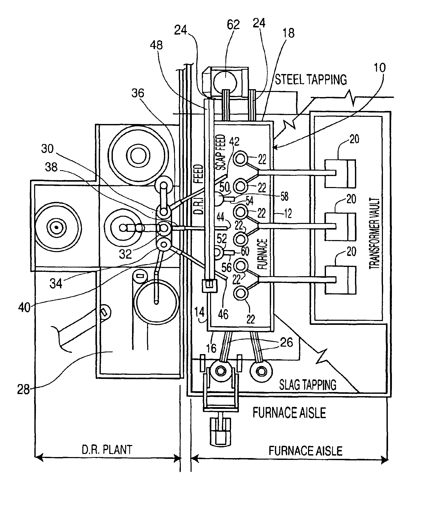
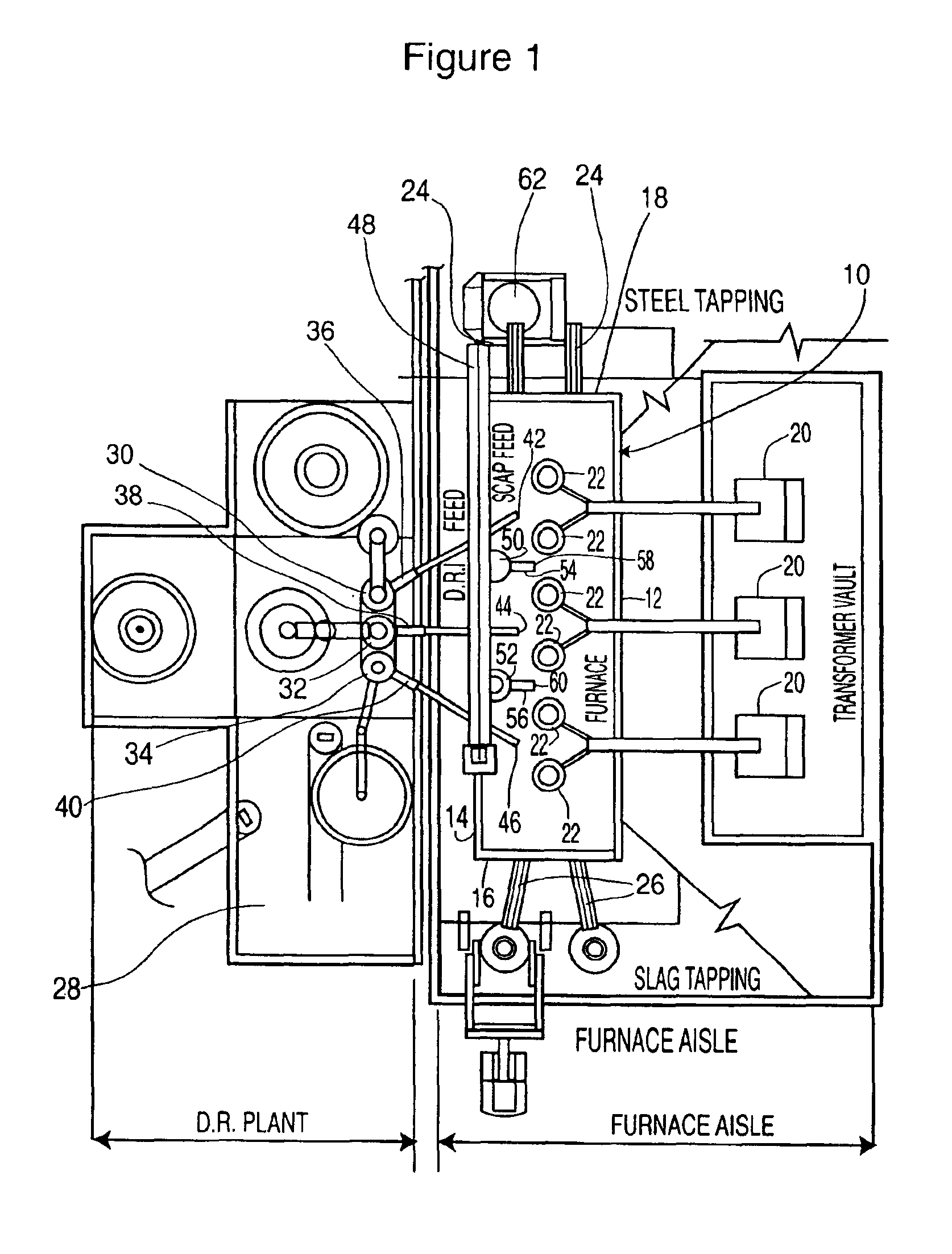
As shown in FIG. 1, the furnace 10 is preferably rectangular in shape, having side walls 12, 14 and end walls 16, 18. The furnace walls and hearth are lined with refractory brick (not shown) which is based on magnesium oxide. In a particularly preferred embodiment of the invention, the furnace may have dimensions of about 9×27 metres, sufficient to provide a relatively large bath size of about 7 to 13 tap volumes, more preferably about 10 tap volumes. The large bath provides a “flywheel” effect, enabling the periodic tapping of steel while continuing to...


PUM

PropertyMeasurementUnit
Temperatureaaaaaaaaaa
Percent by massaaaaaaaaaa

Abstract

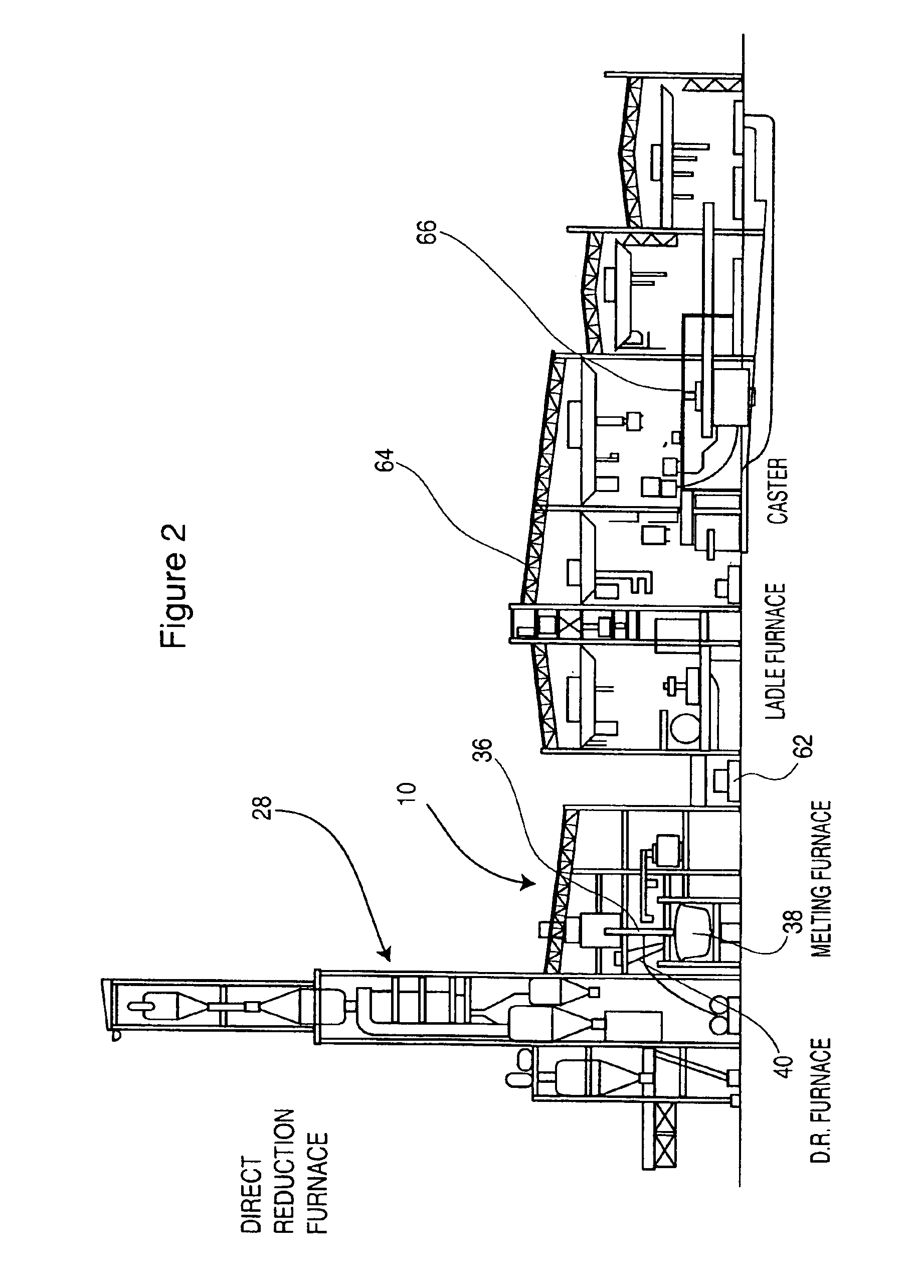
A process for the manufacture of steel in which a charge material comprising direct reduced iron, and optionally containing steel scrap, is continuously charged into a stationary electric arc furnace. Inside the furnace, a bath of molten steel and a continuous slag layer are maintained, the steel bath preferably having a volume of approximately 7 to 13 tap volumes. Heat for melting the charge material is preferably provided by open arcs between the electrodes and the metal bath, with the slag layer preferably being superheated to about 40 to 150° C. above the bath temperature. In order to prevent excessive superheating, the slag preferably has a melting point substantially the same as, or greater than, the bath temperature, with the slag melting temperature being adjustable by varying the amount of MgO in the slag. The slag preferably has low basicity to reduce the rate of refractory erosion. The steelmaking process is preferably carried out in a steel manufacturing plant in which a direct reduction furnace is closely coupled to the electric arc furnace. Preferably, the direct reduction furnace is “stacked” above the electric arc furnace so that the direct reduced iron can be fed to the electric arc furnace by gravity through inclined conduits.

Description

FIELD OF THE INVENTIONThe present invention to relates to steelmaking, and more particularly to continuous processes for steelmaking.BACKGROUND OF THE INVENTIONA challenge facing the steel industry in its never-ending quest for greater efficiency in the development of a continuous steelmaking process. While the upstream iron making and the downstream casting of steel are well-established continuous processes, steelmaking remains essentially a batch operation.Steelmaking is typically conducted in a circular electric arc furnace. Reduced iron in the form of small spheres or briquets, and optionally some steel scrap, is charged into the furnace and melted by very high power electrodes, creating a power density in the furnace hearth of about 2000 to 2500 kW / m2. The molten metal is protected and partly refined by a liquid slag layer comprised primarily of metal oxides. After the charge is melted, the molten metal is poured or tapped from the furnace for subsequent alloying and casting.A ...

Claims


Application Information

Patent Timeline
IPC IPC(8): C21C5/00C21C5/52C21C5/56C21C5/54
CPCC21C5/5294C21C5/567C21C5/54Y02P10/20
Inventor GORDON, IAKOVWHEELER, FRANK M.
Owner HATCH LTD
Learn More