Plasma processor apparatus and method, and antenna

a technology of processors and antennas, applied in the direction of coatings, electric discharge lamps, electric lighting sources, etc., can solve the problems of preventing all practical coils from having the complete cylindrical symmetry, and affecting the uniformity of plasma density

Inactive Publication Date: 2005-04-05
LAM RES CORP
View PDF6 Cites 55 Cited by
  • Summary
  • Abstract
  • Description
  • Claims
  • Application Information

AI Technical Summary

Benefits of technology

One aspect of the invention relates to a plasma processor antenna adapted to be driven by power from an AC source. The antenna comprises first and second excitation terminals adapted to be powered by power from the source and a plasma excitation coil arranged to be energized by power coupled to the first and second excitation terminals via circuitry outside the antenna. The antenna has connections and reactances with values causing current flowing through the excitation terminals via the circuitry outside the antenna to be less than current flowing in a plasma excitation winding of the coil. The antenna excitation terminals are driven by power from the AC source via the circuitry outside the antenna and supply power to circuitry within the antenna.

Problems solved by technology

The very high current in these leads has an adverse effect on the uniformity of the density of plasma 50.
These connections prevent all practical coils from having the complete cylindrical symmetry of the idealized coil.

Method used


Image

  • Plasma processor apparatus and method, and antenna
  • Plasma processor apparatus and method, and antenna
  • Plasma processor apparatus and method, and antenna

Examples


Embodiment Construction

. 3-16

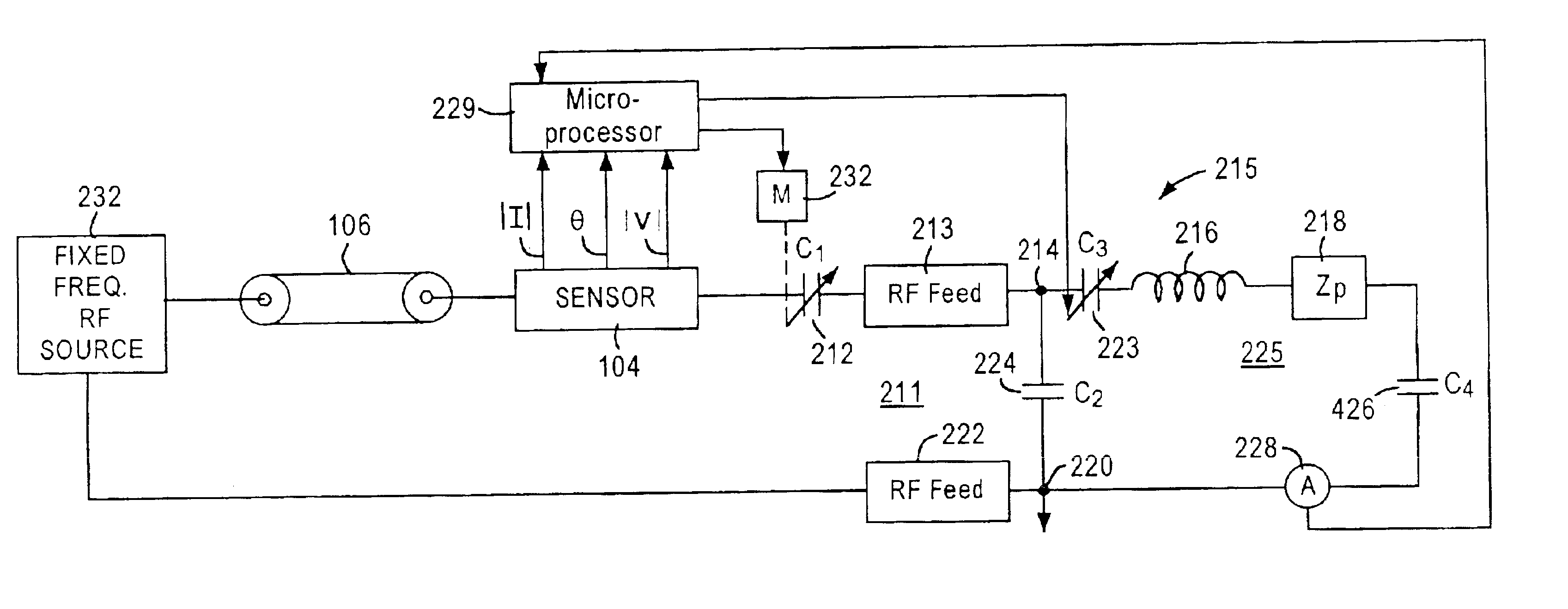
Reference is now made to the schematic diagram of FIG. 3 wherein fixed frequency RF source 232 (typically having a frequency of 4.0 MHz or 13.56 MHz) is illustrated as having an output that drives cable 106, having an output connected, via sensor 104, to one electrode of variable, series connected capacitor 212 of matching network 211. A second electrode of capacitor 212 is connected by current feed or post 213 to excitation terminal 214 of antenna 215, including coil 216; details of antenna 215 are illustrated in FIG. 13. Antenna 215 replaces antenna 48, FIG. 1. A first terminal of coil 216 is connected to grounded excitation terminal 220 via the series connection of ammeter 228 and fixed capacitor 426 (which is the equivalent of capacitor 126, FIG. 1). The impedance of plasma 50 is indicated in FIG. 3 by the series impedance ZP (box 218) between the first end of coil 216 and capacitor 426. Variable capacitor 223, preferably a semiconductor of the type that is electronically ...


PUM

PropertyMeasurementUnit
pressureaaaaaaaaaa
impedanceaaaaaaaaaa
impedanceaaaaaaaaaa

Abstract

An antenna includes excitation terminals responsive to an RF source to supply an RF electromagnetic field to a plasma that processes a workpiece in a vacuum chamber. A matching network includes first and second portions respectively between the source and terminals and between the terminals and the antenna plasma excitation coil. In response to indications of impedance matching between the source and its load, currents flowing between (1) the first portion and the terminals and (2) the terminals and the coil are controlled so the latter exceeds the former. The indications control impedances of the first and second portions or the first portion impedance and the source frequency. The coil can include a transformer having a primary winding coupled to the excitation terminals and a multi-turn plasma excitation secondary winding.

Description

FIELD OF INVENTIONThe present invention relates generally to plasma processor antennas and to a method of and apparatus for operating plasma processors, and more particularly, to a plasma processor antenna having components such that the current flowing in a plasma excitation coil of the antenna exceeds the current flowing in excitation terminals of the antenna. (Hereafter in this document, current refers to RMS current or peak positive or negative current during an AC cycle, unless otherwise noted.) Another aspect of the invention relates to a plasma processor antenna having primary and secondary windings.BACKGROUND ARTA typical prior art workpiece processor, as illustrated in FIG. 1, includes vacuum plasma processing chamber assembly 10, a first circuit 12 for driving a planar excitation antenna 48 consisting of a coil for exciting ionizable gas in chamber assembly to a plasma state, a second circuit 14 for applying RF bias to a workpiece holder in chamber assembly 10, and a contr...

Claims


Application Information

Patent Timeline
Patent Type & Authority Patents(United States)
IPC IPC(8): H01J37/32
CPCH01J37/32183H01J37/321
Inventor HOWALD, ARTHUR M.KUTHI, ANDRAS
Owner LAM RES CORP
Why Eureka
Try Eureka