GMR spin valve structure using heusler alloy

Inactive Publication Date: 2005-04-05
SEAGATE TECH LLC
View PDF16 Cites 26 Cited by
  • Summary
  • Abstract
  • Description
  • Claims
  • Application Information

AI Technical Summary

Benefits of technology

In accordance with one embodiment of the invention, a giant magnetoresistive spin valve sensor is provided, along with a method for making such a sensor, in which a non-ferromagnetic spacer layer is provided between first and second ferromag

Problems solved by technology

In the presence of a magnetic field such as that provided by magnetic storage medium, the resistance of the sensor changes resulting in a change in voltage across the se

Method used


Image

  • GMR spin valve structure using heusler alloy
  • GMR spin valve structure using heusler alloy
  • GMR spin valve structure using heusler alloy

Examples


Embodiment Construction

The present invention relates to magnetoresistive sensors of the giant magnetoresistive (GMR or spin valve) type which are used to read back information from storage media such as magnetic discs. One aspect of the present invention includes a GMR sensor having ferromagnetic layers of Heusler alloy can be achieved by at least partially matching the energy bands of a non-ferromagnetic spacer to the energy bands for one of the spin states (majority or minority) of the ferromagnetic layers.

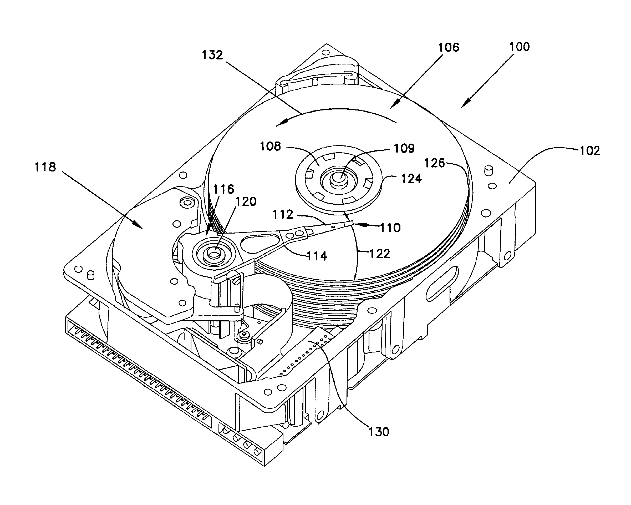
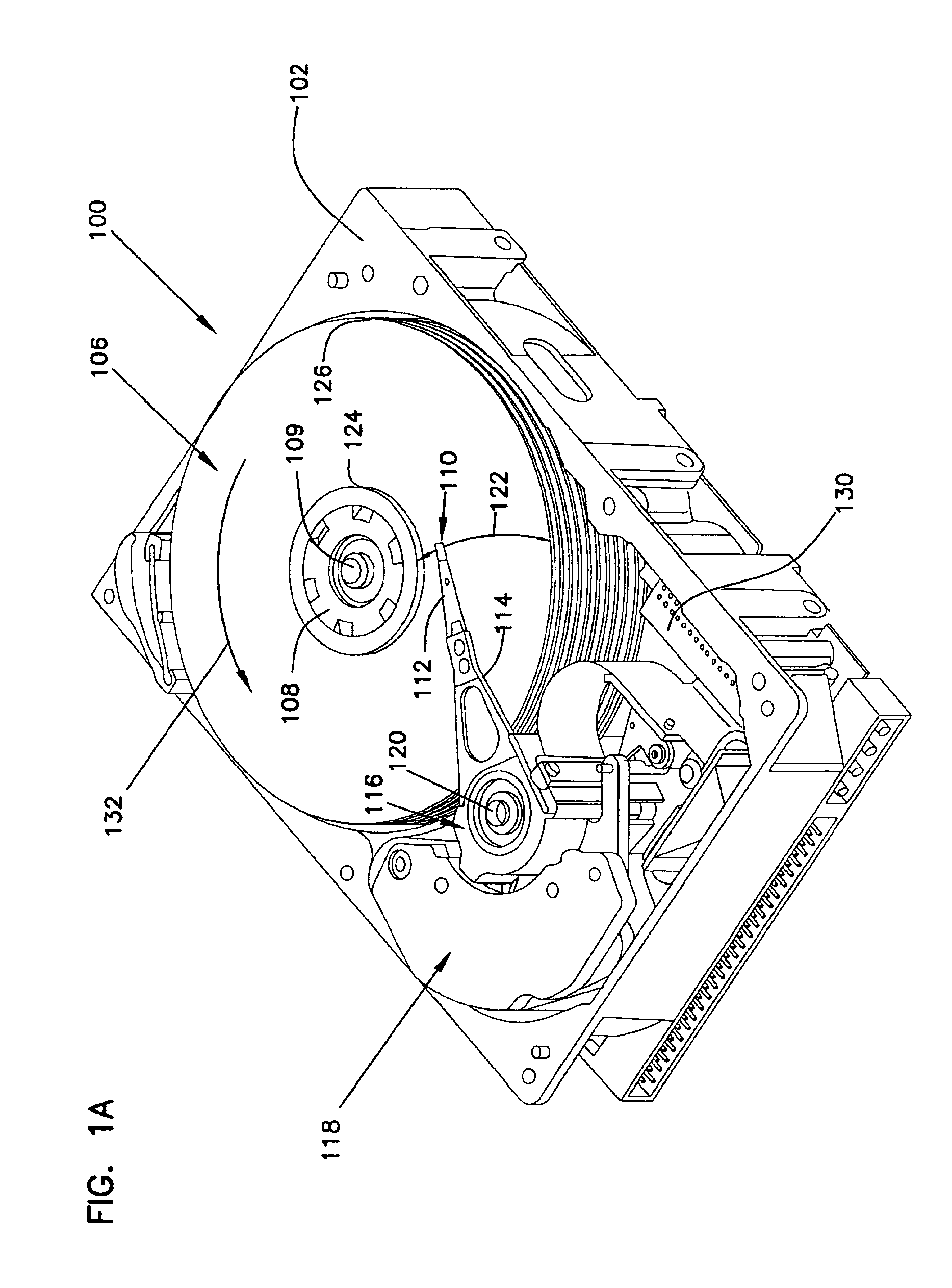
FIG. 1A is an isometric view of a disc drive 100 in which embodiments of the present invention are useful. Disc drive 100 includes a housing with a base 102 and a top cover (not shown). Disc drive 100 further includes a disc 106, which is mounted on a spindle motor (not shown) by a disc clamp 108. Disc 106 is part of a disc pack which includes a plurality of individual discs (storage media), which are mounted for co-rotation about central axis 109. Disc 106 has an associated disc head slider 110 which...


PUM


Abstract

A giant magnetoresistive spin valve sensor is provided in which first and second ferromagnetic layers comprise a Heusler alloy. A non-ferromagnetic spacer layer is positioned between the first and second ferromagnetic layers. The non-magnetic spacer layer has an energy band which is similar to the energy bands of the Heusler alloy of the first and second ferromagnetic layers to allow a giant magnetoresistive effect to occur.

Description

FIELD OF THE INVENTIONThe present invention relates to magnetic sensors. More particularly, the present invention relates to giant magnetoresistive (GMR) spin valve magnetoresistive sensors.BACKGROUND OF THE INVENTIONMagnetic sensors utilizing the GMR effect, frequently referred to as “spin valve” sensors, are known in the art. A spin valve sensor is typically a sandwiched structure consisting of two ferromagnetic layers separated by a thin non-ferromagnetic layer. One of the ferromagnetic layers is called the “pinned layer” because it is magnetically pinned or oriented in a fixed and unchanging direction by an adjacent anti-ferromagnetic layer, commonly referred to as the “pinning layer,” through anti-ferromagnetic exchange coupling. The other ferromagnetic layer is called the “free” or “unpinned” layer because the magnetization is allowed to rotate in response to the presence of external magnetic fields.In a giant magnetoresistive sensor, a sense current is applied to the sensor a...

Claims


Application Information

Patent Timeline
IPC IPC(8): G01R33/06G01R33/09H01F41/30H01F10/00H01F41/14G11B5/39H01F10/32G11B5/00G11B5/012
CPCB82Y10/00B82Y25/00B82Y40/00G01R33/093H01F41/307G11B5/3903H01F10/3213H01F10/3268G11B5/00G11B2005/3996G11B5/012
Inventor AMBROSE, THOMAS F.MRYASOV, OLEG N.
Owner SEAGATE TECH LLC
Why Eureka
Try Eureka