Variable motion system and method

a technology of variable motion and motion system, applied in the field of variable motion system and method, can solve the problems of inordinately high downtime for maintenance and/or repair of these prior art systems, and achieve the effect of saving time and money

Inactive Publication Date: 2005-04-05
TETRA LAVAL HLDG & FINANCE SA
View PDF123 Cites 229 Cited by
  • Summary
  • Abstract
  • Description
  • Claims
  • Application Information

AI Technical Summary

Benefits of technology

The present invention now provides a system for use in a manufacturing operation, production process, or other process or operation comprising a plurality of movable elements that are constrained for movement along a path and wherein the position of each of the movable elements along the path is controlled independe

Problems solved by technology

This situation relies upon mechanical aspects of the system such as the precision of operation of the conveyor, the accuracy with which the conveyor can be stopped at a work station and started for movement to a further work

Method used


Image

  • Variable motion system and method
  • Variable motion system and method
  • Variable motion system and method

Examples


Embodiment Construction

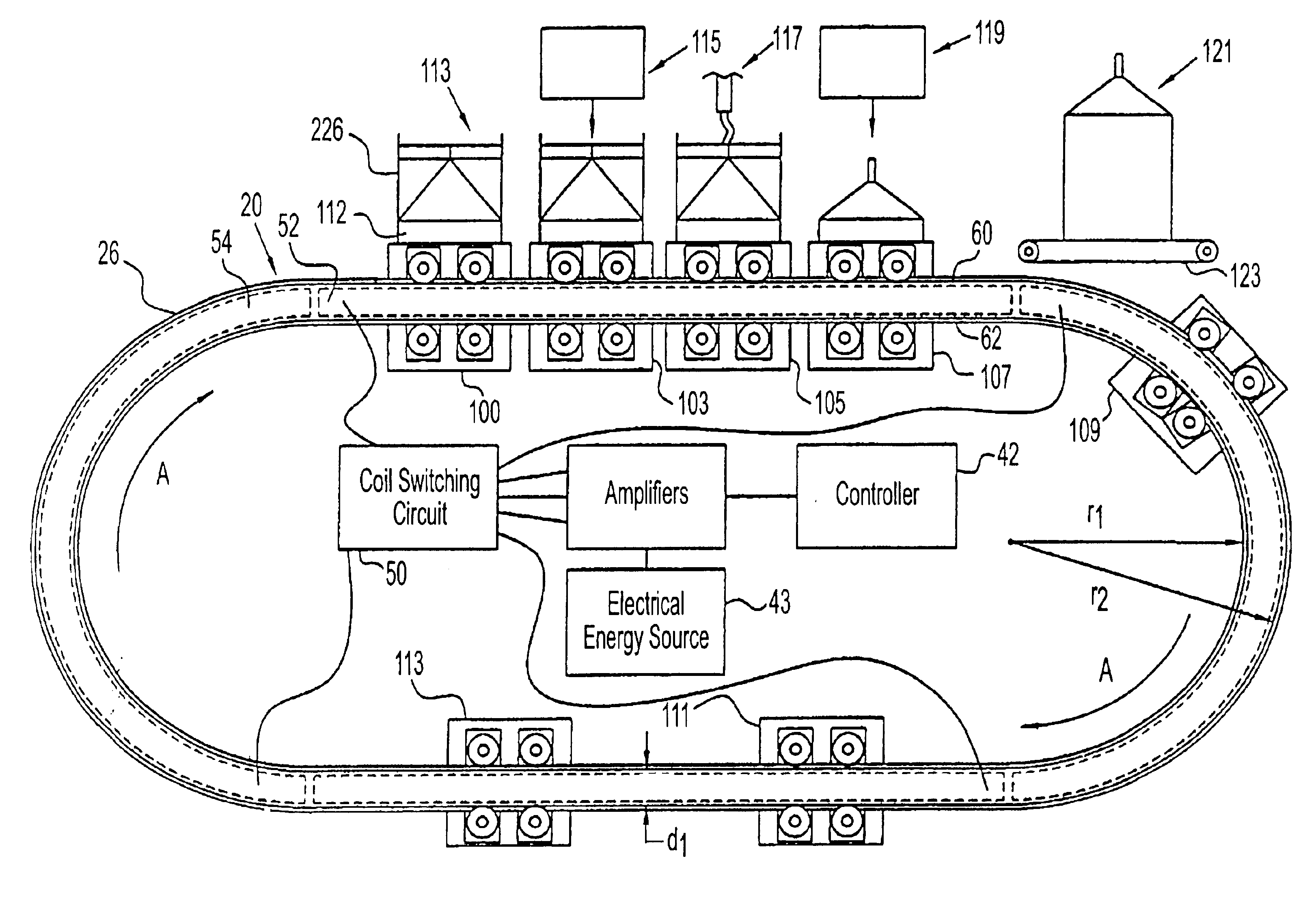
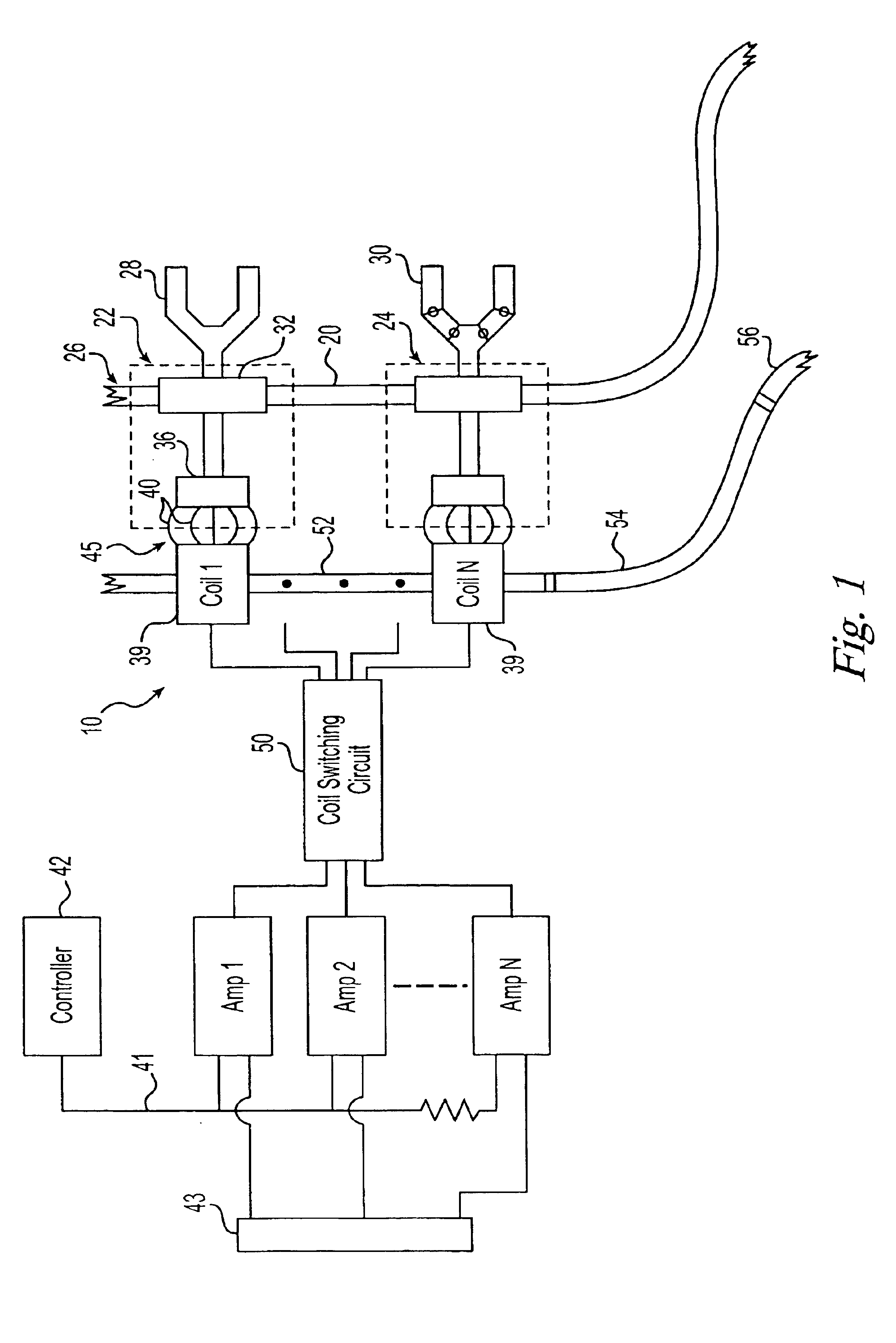
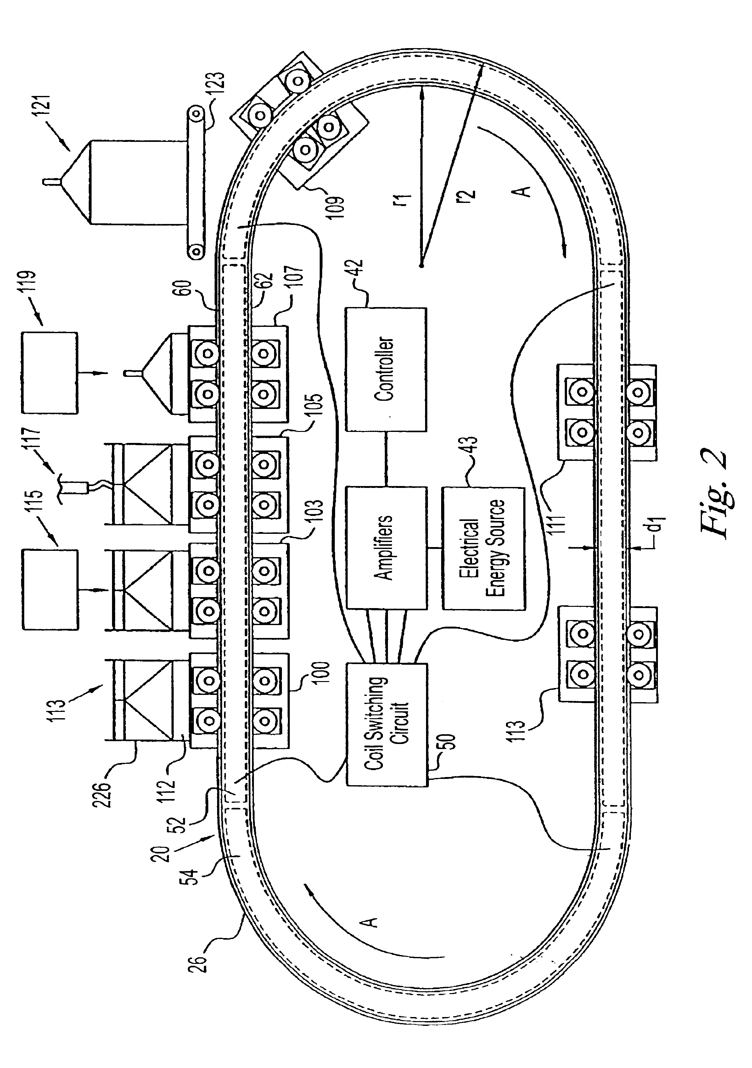
The system of the present invention may be employed in an “open loop” or a “closed loop” configuration. “Open loop” refers to a control system in which there is no feedback as to the position, velocity, acceleration, direction, force, torque, jerk, and / or other motion parameters (hereinafter “control variable”) of a movable element at any given point in time. In an “open loop” system, each of the movable elements is controlled positionally along a path by appropriate electrical energy being supplied to individual ones of the coils located along the path. The nature of the electrical energy applied to the coils determines what reaction the reactive element of the system will exhibit. Position or other motion parameters are not monitored. In a “closed loop” system, a feedback arrangement is provided which signals the position, velocity, acceleration, direction, force, torque and / or jerk, or other motion parameters, of each of the plurality of movable elements at a given time. This fee...


PUM

PropertyMeasurementUnit
Timeaaaaaaaaaa
Forceaaaaaaaaaa
Accelerationaaaaaaaaaa

Abstract

The invention relates to a system and a method for performing a manufacturing operation at a predetermined position relative to a first path. The system includes a plurality of first elements mounted for movement relative to the first path. The first elements have a plurality of motion parameters which are independently controllable. Active elements are operatively associated with reactive elements to produce relative movement between the first elements and the first path, with the active elements controlling the relative movement. A controller controls the activation of the active elements and a first tool is associated with each first element for performing at least part of the manufacturing operation. The system may also include at least one second element and a second path. The method includes the steps of mounting a plurality of first carriages for movement relative to a first path, operatively associating a plurality of active elements with at least one reactive element to produce relative movement between the first carriages and the path, associating a first tool with each first carriage for performing at least part of the manufacturing process, and controlling the activation of the active elements.

Description

FIELD OF THE INVENTIONThe present invention relates to a variable motion system and method for providing controlled positioning of a plurality of movable elements as components. In particular, the present invention relates to utilizing a linear motor to independently control and position a plurality of movable elements along a path in a production process or manufacturing environment so that work may be performed during the process.BACKGROUND OF THE INVENTIONMovable elements are often provided as part of an overall machine, device or system, such as a production process or manufacturing environment. In this type of process or environment, it is desirable that all of the movable elements be mounted for movement along one or more defined paths, that all of the elements be movable independently of others of the movable elements, and that the movement of all of the movable elements be controlled independently of the other movable elements, subject to the limitation that no two movable e...

Claims


Application Information

Patent Timeline
IPC IPC(8): B29C65/00B29C65/02B65B9/20B65B51/30
CPCB29C65/02B29C66/4322B29C66/1122B29C66/8226B29C66/8351B29C66/872B29C66/98B65G54/02B29C65/7879B29C66/4312B29C66/83413B29C66/83415B29C66/8491B65B9/20B65B51/306B29C65/00B29C65/7867B29C65/7897B29C66/43121B29C66/43122B29C66/81871B29C66/82263B29L2031/7166
Inventor ORTIZ, MARK S.BOGDANOV, EMIL D.NAJI, MOHAMMAD R.JACOBS, KEITH G.BOLOGNA, GREGORY A.ARMS, DONALD A.
Owner TETRA LAVAL HLDG & FINANCE SA
Why Eureka
Try Eureka