Roller cam buckle

a rolling cam and buckle technology, applied in the direction of snap fasteners, fastening devices, transportation items, etc., can solve the problems of inability to obtain satisfactory tension force, inability to apply enough pulling force fp to obtain the required tension force, and high cost of manufacture and sale of ratchet type buckles. achieve the effect of increasing tension, reducing friction in the cam buckle, and increasing tension

Inactive Publication Date: 2005-04-12
SIMONSON ERIC +1
View PDF53 Cites 50 Cited by
  • Summary
  • Abstract
  • Description
  • Claims
  • Application Information

AI Technical Summary

Benefits of technology

The present invention relates to a method and apparatus for reducing friction in a cam buckle for tightening a strap. The cam buckle includes a frame, a brake member, a roller member, a biasing element and a webbed strap. The brake member includes a serrated surface and is rotatably coupled to the frame and pivotal about a first axis. The roller member is rotatably coupled to the frame about a second axis, wherein the first axis and the second axis are substantially parallel to each other. The biasing element is operable to bias the serrated surface of the brake member toward the roller member. The webbed strap is formed from a polymeric material and is operable to be biased between the serrated surface and the roller member so that the brake member biases the webbed strap against the roller member. With this arrangement, when the webbed strap is placed in tension, such tension is maintained by preventing movement of the webbed strap in one direction and allowing movement in a second direction to increase the tension. The roller member is operable to rotate with movement of the webbed strap in the second direction to increase the tension in the webbed strap which facilitates a reduction in friction loss.

Problems solved by technology

One problem with the static cam buckle 10 is that the user cannot apply enough pulling force Fp to obtain the required tension force Ft that may be needed to secure a given load.
Often it is physically impossible to obtain a satisfactory tension force Ft.
However, these ratchet type buckles are much more complex than the static cam buckles and are more expensive to manufacture and sell.
Further, such complex ratchet buckles can have a higher failure rate over time than that of the static cam buckles.

Method used


Image

  • Roller cam buckle
  • Roller cam buckle
  • Roller cam buckle

Examples


Embodiment Construction

Reference will now be made to the exemplary embodiments illustrated in the drawings, and specific language will be used herein to describe the same. It will nevertheless be understood that no limitation of the scope of the invention is thereby intended. Alterations and further modifications of the inventive features illustrated herein, and additional applications of the principles of the inventions as illustrated herein, which would occur to one skilled in the relevant art and having possession of this disclosure, are to be considered within the scope of the invention.

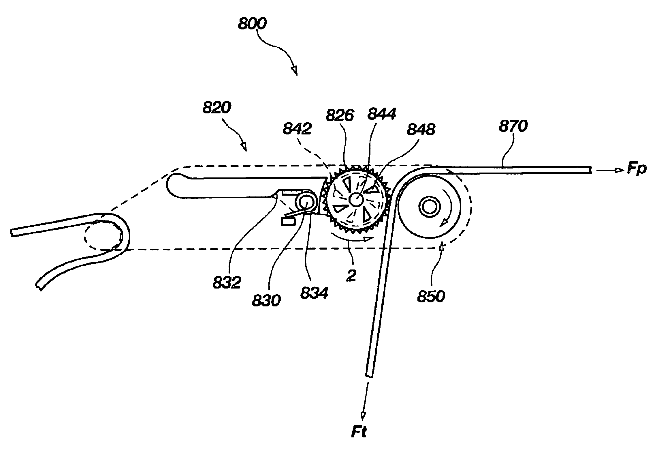
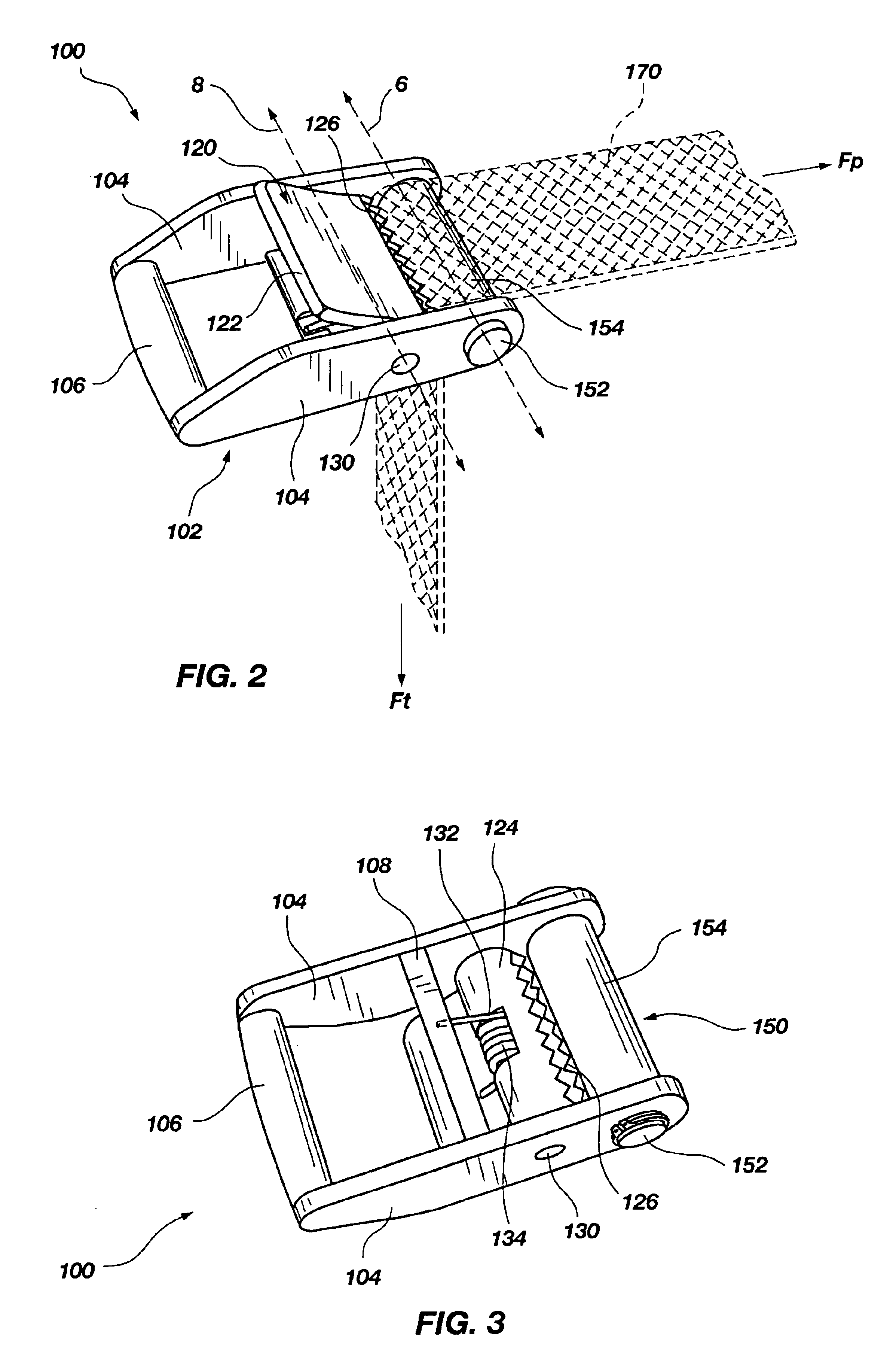
FIGS. 2, 3 and 4 illustrate various views of a roller cam buckle 100 according to an embodiment of the present invention. Such a roller cam buckle 100 can be utilized for, and associated with, strapping objects, cargo, backpacks, bags or the like. Further, the roller cam buckle 100 can be configured with a single strap associated with the roller cam buckle and / or a double strap associated with the roller cam buckle.

The...


PUM


Abstract

A method and apparatus for reducing friction in a cam buckle for tightening a strap. The cam buckle includes a frame, a brake member, a roller member, a biasing element and a webbed strap. The brake member includes a serrated surface and is rotatably coupled to the frame and pivotal about a first axis. The roller member is rotatably coupled to the frame about a second axis, wherein the first axis and the second axis are substantially parallel to each other. The biasing element is operable to bias the serrated surface of the brake member toward the roller member. The webbed strap is formed from a polymeric material and is operable to be biased between the serrated surface and the roller member so that the brake member biases the webbed strap against the roller member. With this arrangement, when the webbed strap is placed in tension, such tension is maintained by preventing movement of the webbed strap in one direction and allowing movement in a second direction to increase the tension. The roller member is operable to rotate with movement of the webbed strap in the second direction to increase the tension in the webbed strap.

Description

FIELD OF THE INVENTIONThe present invention relates generally to strap securing devices and, more particularly, the present invention relates to a roller cam buckle that reduces exertion force for cinching and securing objects in place with a strap.RELATED ARTThe use of straps to secure objects and cargo is well known in the art. Mechanical advantages to increase the tension force securing the object, for a given pulling force exerted by the operator have been provided over the years. Buckles have been designed and manufactured that allow for a cinch to apply tension force on the strap. The tension force applied to the strap through the buckle secures the cargo. A self locking mechanism allows the operator to apply a pulling force on the strap and “lock in” the tension force on the other side of the buckle when the pulling force is removed. In general for a single self locking cam buckle, the pulling force will always be greater than the tension force due to high friction losses in ...

Claims


Application Information

Patent Timeline
Patent Type & Authority Patents(United States)
IPC IPC(8): B60P7/08B60P7/06
CPCB60P7/083Y10T24/4016Y10T24/40Y10T24/2175
Inventor SIMONSON, ERICSIMONSON, ROGER
Owner SIMONSON ERIC
Why Eureka
Try Eureka