Device and method for fixation of airframe pieces

a technology for fixing devices and airframes, applied in process and machine control, process control, instruments, etc., can solve the problems of large number of fixed work fixtures, fixed work fixtures designed for specific craft cannot be reused, and cannot be used for airframes

Inactive Publication Date: 2005-04-12
SAAB AB
View PDF8 Cites 18 Cited by
  • Summary
  • Abstract
  • Description
  • Claims
  • Application Information

AI Technical Summary

Benefits of technology

When all fixing elements are positioned a frame is fixed to the fixing elements of each main rail after which an airframe skin is held in place against the frames by chucking to allow assembly of the frames and the skin. Conversely, an airframe skin can naturally be fastened to and be supported by the fixing elements, after which the given number of frames are braced to the skin, thus ensuring that skin and frames are fixed in relation to one another during assembly of these parts.
An advantage of this method of assembly is that the device allows variable setting of the fixing elements.
An advantage of this locking function arrangement, where the power to unlock the lock is conveyed via the manipulator, is that there is no need for cabling inside the device, which would otherwise be required for transferring power to each individual lock.
Other advantages of the method and the device in accordance with the invention is that the device can be simply and quickly adjusted for new types of airframe. Consequently, the device may be used for more than one series of airframe, and in addition, it allows an airframe to be altered relatively easily and cheaply after production of a number of units in a model series. Furthermore, the same device can be used for different sections of the same airframe. The device may also be used in the future for products that at present have not yet been developed, and so can be used over a long period. Thus, such a device would be attractive in the small-scale production of vehicles and other structures, where it is not economically viable to employ fixed work fixtures or expensive semi-flexible solutions. In the case where an industrial robot is used as a manipulator for regulating the device, the invention method is particularly useful, since such an industrial robot may be used for other types of work when regulating the device is not being carried out. Examples of such work are programmed drilling, riveting, and grinding on the actual structure or airframe that is fixed to the device.

Problems solved by technology

Fixed conventional work fixtures as described above can only be used for a specific airframe section, which means that a large number of these fixed work fixtures are needed and that they can only be used for the aircraft for which they were originally produced.
This is very expensive, which means that fixed work fixtures can only be used for airframes that are mass-produced.
In principle, a fixed work fixture designed for a specific craft can never be reused, and as a result is scrapped when production of the aircraft has been terminated.
Although to some extent the described device allows the points of attachment to be individually set, the device is only partly flexible.
A disadvantage of the semi-flexible solution described here is the high cost since each rod referred to above is supplied with a separate controlling mechanism for positioning the fixing element at its right height.
Furthermore, there are practical difficulties caused by the plethora of cables attached to each rod for power supply and for controlling the positioning mechanism.
Nor does the technical solution involving placing the said rods in the said rows according to a matrix permit variable setting of the fixing elements' positions.
A disadvantage of this semi-flexible device is still that the position of the rods in the horizontal plane can not be varied freely.
Moreover, the portal robot that is used is expensive and cannot be used for tasks other than those mentioned, i.e. a manipulator in the form of the portal robot is just as specialised as the device itself.

Method used


Image

  • Device and method for fixation of airframe pieces
  • Device and method for fixation of airframe pieces
  • Device and method for fixation of airframe pieces

Examples


Embodiment Construction

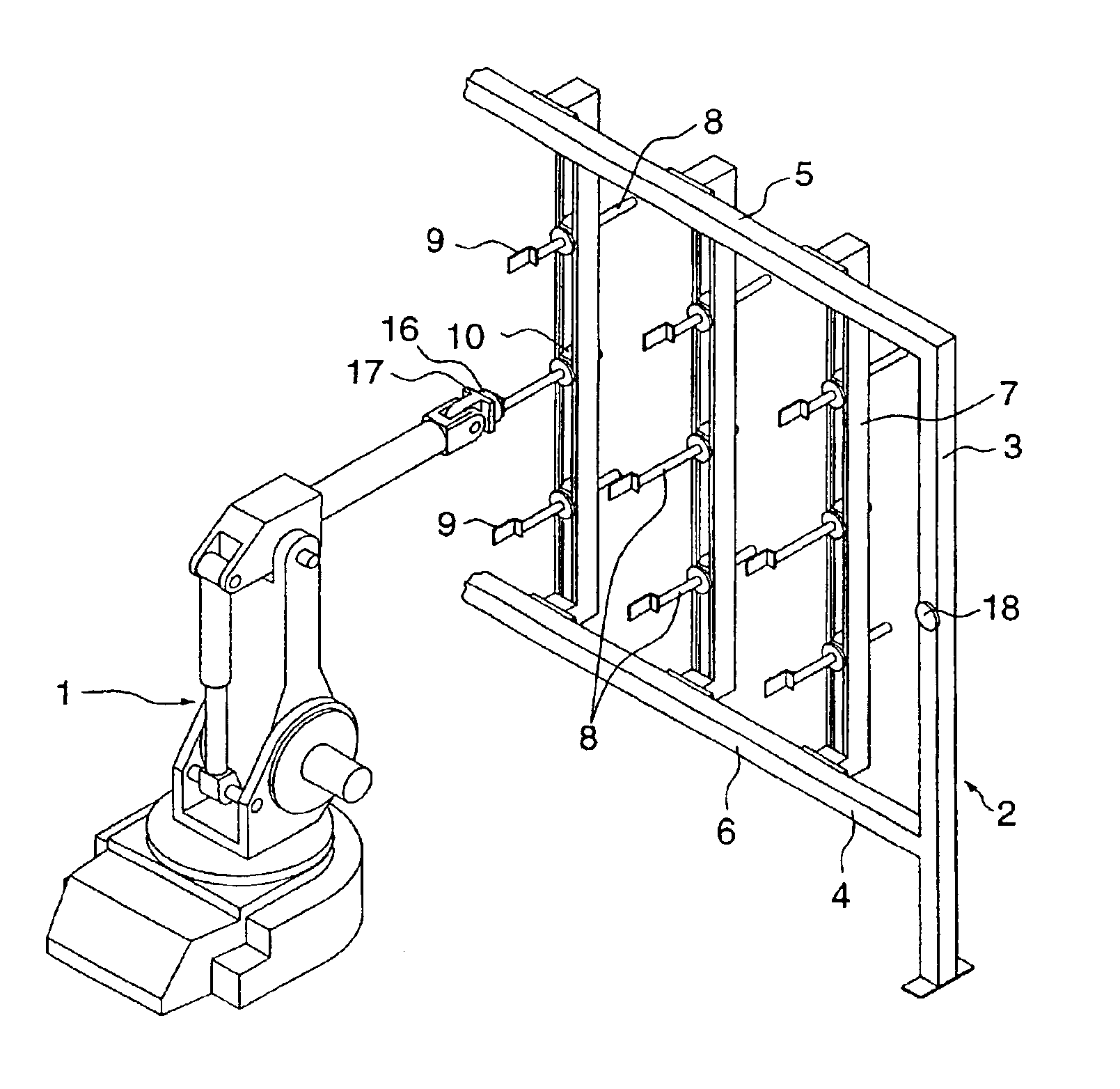
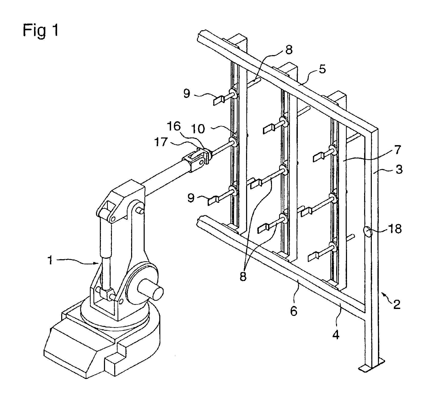
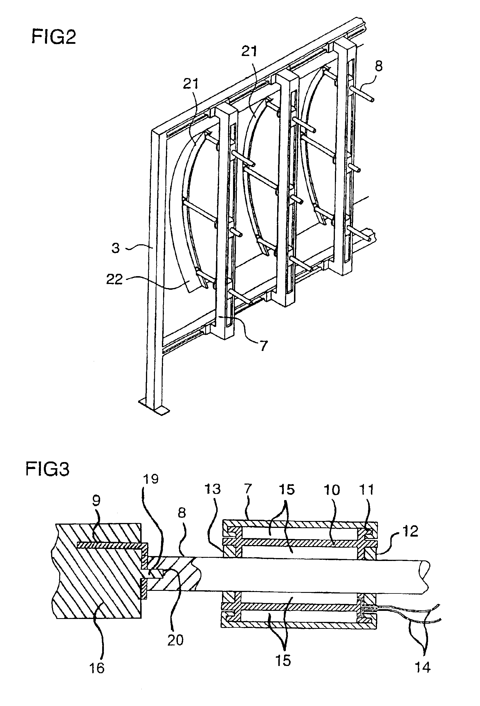
According to an aspect of the invention a method is provided for regulating a device used for assembling aircraft airframe pieces, where the device consists of a rig comprising parallel main rails that can slide parallel to each other along the rig along a first co-ordinate x, and where each main rail has a number of parallel guide rails which can slide parallel to each other along the main rail along a second co-ordinate y, and where in addition each guide rail can slide axially along a third co-ordinate z, with a fixing element at the end of the guide rail, and where the method involves a manipulator grasping a guide rail's fixing element after which the fixing element is moved by the manipulator in directions x, y and z so that the fixing element is made adopt a predetermined position in space, and while the fixing element is moving:the main rail to which the fixing element is connected is slid parallel to the x direction when the manipulator sets the fixing element at a given x ...


PUM

PropertyMeasurementUnit
volumeaaaaaaaaaa
electricalaaaaaaaaaa
semi-flexibleaaaaaaaaaa

Abstract

A method for regulating a device used for fixing aircraft airframe pieces in connection with assembly of airframe parts, where the device consists of a rig comprising a matrix of rails that can slide in such a way that a number of fixing elements attached to the rails can be positioned freely along three co-ordinates x, y, z in space within a given volume, where a manipulator grasps a fixing element after which the fixing element is moved by the manipulator to the given co-ordinate, and where the rails on which a fixing element is arranged is locked in relation to the rig by an automatic locking function initiated by the manipulator, thereby fixing the fixing element's position in space and the setting procedure is repeated for a predetermined number of fixing elements on the rig.

Description

TECHNICAL FIELDThe invention relates to a device and a method for regulating a device designed, for example, for holding a number of aircraft frames fixed in a predetermined position and for fixing the skin of the airframe in a predetermined position to allow the skin and the frames to be put together to produce an airframe section. The device can also be used to hold the airframe section in a predetermined position when parts are being fastened to the airframe section.STATE OF THE ARTIn the production of airframes, there is a need for some form of work fixture or jig, designed in such a way that the frames and the skin of a airframe section can be held firmly in place, at least at a number of points within a given volume, so that the frames can be fixed in predetermined positions and so that the skin of the airframe section can be applied to, fastened to and be held in place against the frames while the frames and the airframe skin are being fastened together. In the production of ...

Claims


Application Information

Patent Timeline
Patent Type & Authority Patents(United States)
IPC IPC(8): B25B11/00B25B5/00B64C1/12B64C1/00B64F5/00
CPCB25B5/003B25B11/00B64C1/12B64F5/0009Y10S269/909G05B2219/49025Y10T29/49998Y10T29/53039Y10T29/53974Y10T29/4978Y10T29/53961Y10T29/53978Y10T29/49778B64F5/10
Inventor ENGSTROM, MAGNUSKARLSSON, MATSKVIST, ROLAND
Owner SAAB AB
Why Eureka
Try Eureka