
Method of manufacturing an ink jet head

a manufacturing method and jet head technology, applied in the field of ink jet head and ink jet head apparatus, can solve the problems of unstable ink discharge, non-uniform or degrading recording quality, etc., and achieve the effect of convenient alignment, accurate alignment and accurate alignmen

Inactive Publication Date: 2005-04-12
CANON KK
View PDF25 Cites 0 Cited by
  • Summary
  • Abstract
  • Description
  • Claims
  • Application Information

AI Technical Summary

Benefits of technology

In view of the aforementioned problems, an object of the present invention is to provide an ink jet head and an ink jet apparatus which avoid or at least reduce the loss of discharge energy which would otherwise escape to adjacent ink flow passages, ensuring excellent discharge.
Consequently, a positional deviation of, for example, the ceiling plate can be reduced. Further, since discharge energy losses to the adjacent flow passages can be reduced, discharge can be performed in a state wherein there is substantially no crosstalk between the adjacent flow passages, stabilizing discharge. As a result, excellent recording results, such as a fixed dot size, can be obtained.
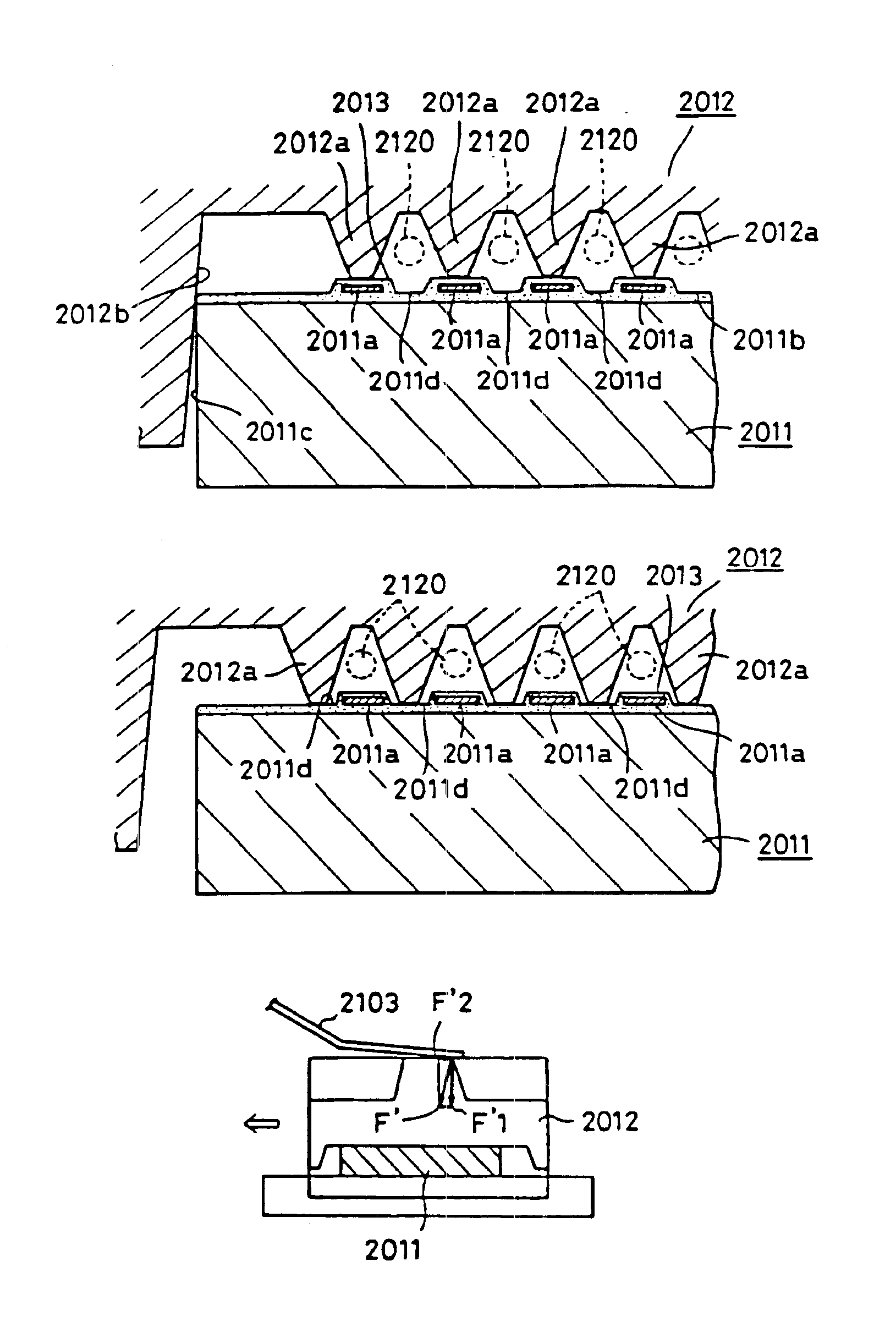
In the present invention, even if accurate alignment is not achieved when the ceiling plate is joined to the heater board, the flow passage walls of the ceiling plate enter the recessed portions provided in the heater board by causing a force in a direction in which the energy generating elements are arranged to act on the ceiling plate. Consequently, the ink discharge ports can be brought into accurate alignment with the energy generating elements.
As a result, alignment can be readily performed using a simple structure, and cost and time required for manufacturing ink jet heads can thus be reduced.

Problems solved by technology

This makes ink discharge unstable.
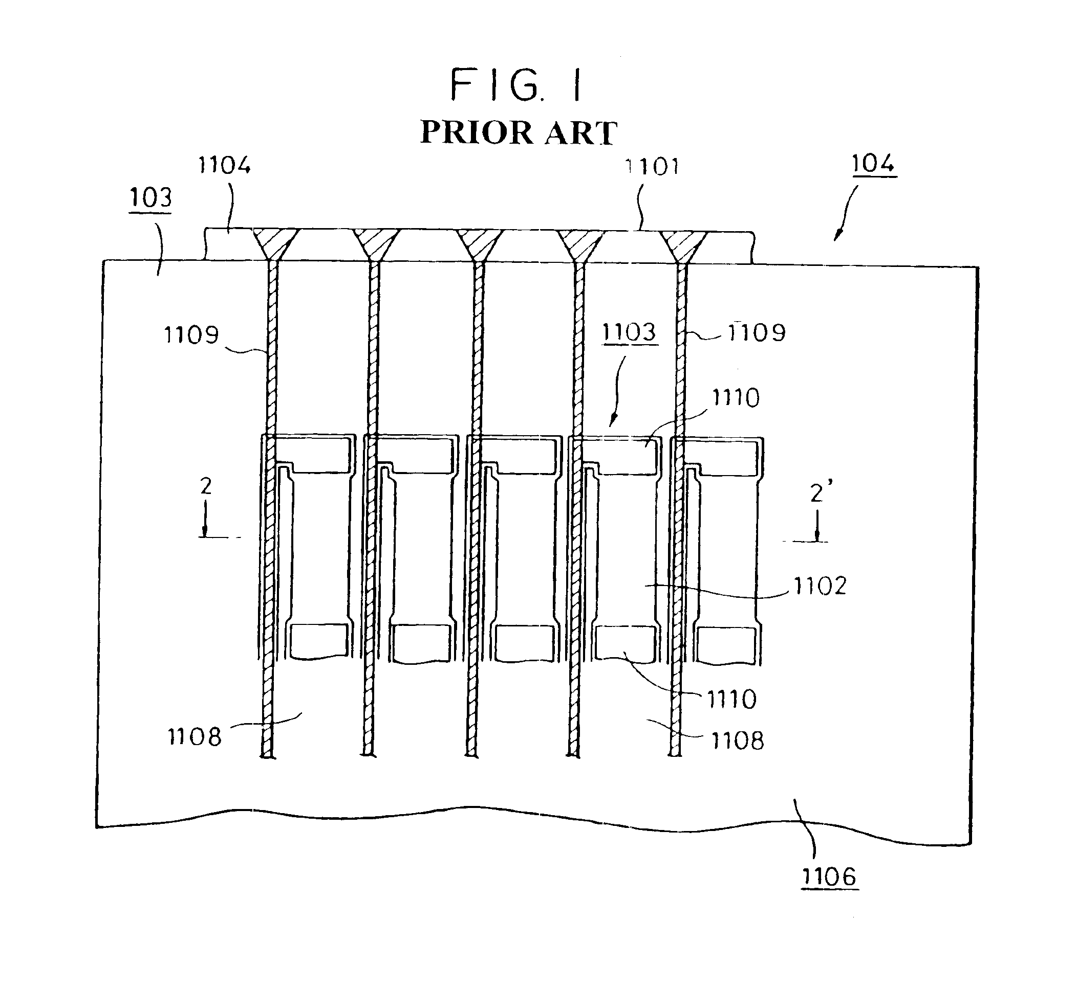
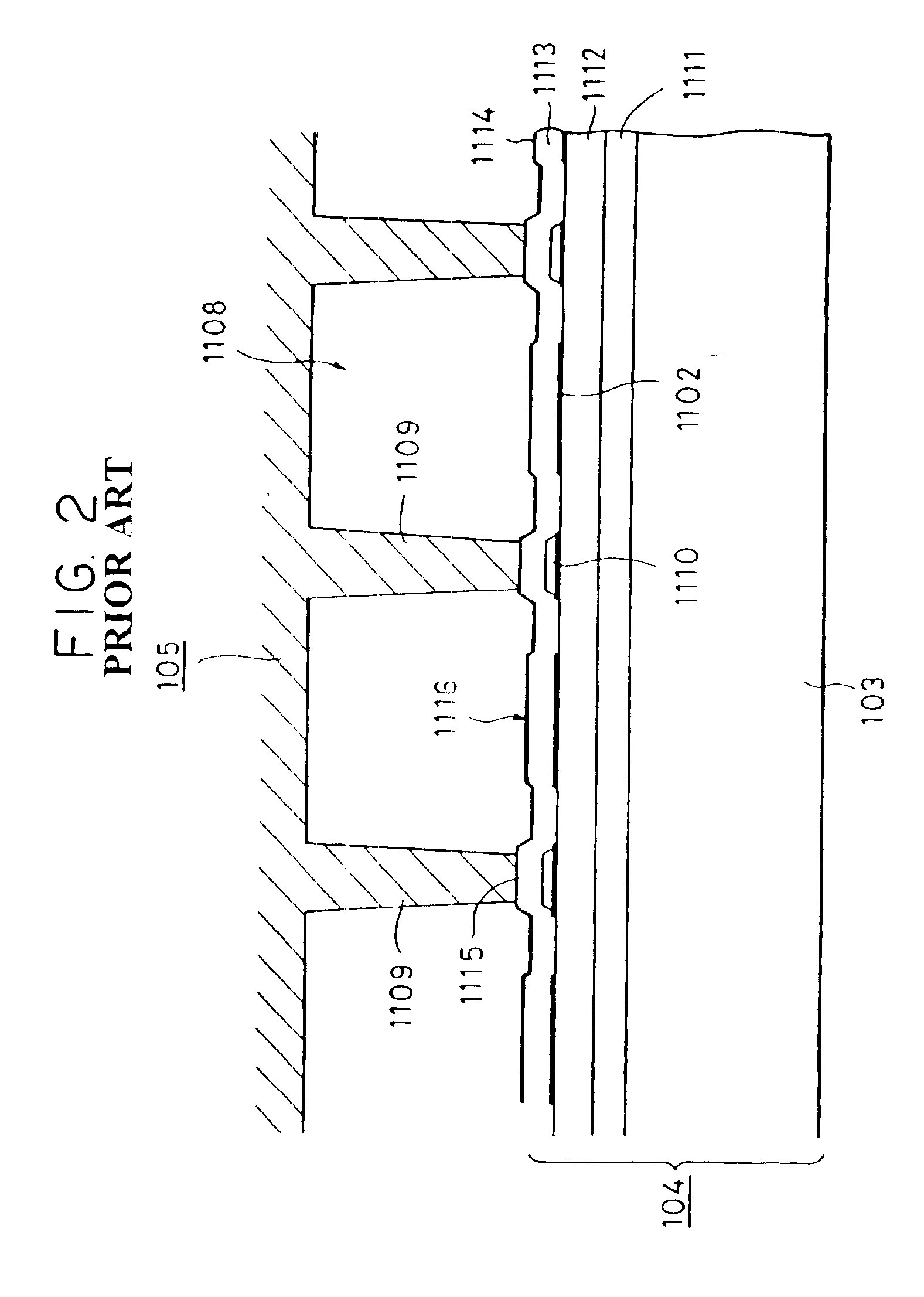
Particularly, this becomes a serious problem in a case where the electro-thermal transducers 1103 and the flow passage walls 1109 are provided close to each other as a consequence of an increase in the resolution of the ink jet head.
In these cases, unstable bubbling, transfer of the bubbling energy into the adjacent ink flow passages or crosstalk may occur, making the dot diameter non-uniform or degrading the recording quality.

Method used


Image

  • Method of manufacturing an ink jet head
  • Method of manufacturing an ink jet head
  • Method of manufacturing an ink jet head

Examples


first embodiment

FIG. 3 is a schematic perspective view of an ink jet head according to the present invention. FIG. 4 is a cross-section taken along the line 4-4′ of FIG. 3. FIG. 5 is a cross-section taken along the line 5-5′ of FIG. 3. FIG. 6 is a cross-section taken along the line 6-6′ of FIG. 5. FIG. 7 is a perspective view of an ink jet cartridge in which the ink jet head shown in FIG. 3 is incorporated. FIG. 8 is an exploded perspective view of the ink jet cartridge shown in FIG. 7. FIG. 9 illustrates a portion of the ink jet cartridge 11 shown in FIG. 7 on which an ink jet unit 13 of an ink tank 14 is mounted.

An ink jet cartridge 11 includes an ink jet head 12 in which the large number of discharge ports 1101 are formed, an ink jet unit 13 which contains the ink jet head 12 and in which electrical interconnections connected to the ink jet head 12 and ink conduits are formed, and an ink tank 14 serving as an ink accommodating portion for accommodating an ink. The ink jet cartridge 11 has an ink...

second embodiment

FIG. 12(A) is a plan view of the heater board according to the present invention. FIG. 12(B) is a cross-section taken along the line 12B-12B′ of FIG. 12(A). Reference numerals in these figures which are the same as those in FIGS. 5 and 6 represent similar or identical elements, and description thereof is thus omitted.

In this embodiment, patterns of films are formed by the known film-forming and etching technologies in the same manner as that of the first embodiment. In this embodiment, since the two heating resistors 1102 are series-connected to each other in the single ink flow passage, the heater board can be formed without disposing the interconnection 1110 in the joining portion of the flow passage wall. Consequently, the recessed portion on the heater board can be formed deeper, and release of the bubbling energy to the adjacent ink flow passages can be further restricted by making such a deep recessed portion the joining portion. As a result, stable discharge can be performed,...


PUM

PropertyMeasurementUnit
Areaaaaaaaaaaa
Energyaaaaaaaaaa
Photosensitivityaaaaaaaaaa

Abstract

A method of manufacturing an ink jet head having a substrate that has a plurality of energy generating elements used for generating energy that in turn is used to discharge ink. The substrate has recessed portions separating the energy generating elements, and a wall member is provided having depending flow passage walls which are joined respectively to the recessed portions. The energy generating elements act on the ink and discharge it through the flow passages.

Description

BACKGROUND OF THE INVENTION1. Field of the InventionThe present invention relates to an ink jet head and an ink jet head apparatus having the ink jet head. Furthermore, the present invention relates to a method of and an apparatus for manufacturing the ink jet head, and more particularly, to the alignment in manufacture of energy generating elements employed for discharge in the head.2. Description of the Related ArtFIGS. 1 and 2 show an example of a conventional ink jet head. FIG. 1 is a longitudinal cross-sectional view partially showing a surface of a head which is cut horizontally along a discharge port row. FIG. 2 is a cross-section taken along the line 2-2′ of FIG. 1.As shown in FIG. 1, a plurality of discharge ports 1101 are provided in a conventional ink jet head. An electro-thermal transducer for generating thermal energy utilized to discharge a liquid (hereinafter referred to as an ink) from the discharge port 1101 is provided for every ink flow passage 1108. Each of the e...

Claims


Application Information

Patent Timeline
IPC IPC(8): B41J2/16
CPCB41J2/14129B41J2/1604B41J2/1623B41J2/1626B41J2/1631B41J2/1634B41J2/1637B41J2/1646B41J2/1635Y10T29/49083B41J2002/14362Y10S29/046Y10T29/49895Y10T29/49401
Inventor SUGITANI, HIROSHIKASAMOTO, MASAMIORIKASA, TSUYOSHIMIYAGAWA, MASASHIKAWAI, JUNARASHIMA, TERUOIZUMIDA, MASAAKI
Owner CANON KK
Learn More