Well car with cross member and method

a cross-member and well-car technology, applied in wagons/vans, metal rolling arrangements, carriages, etc., can solve the problems of affecting the performance of the rail road well car, increasing the weight of the side beam, and imposing a bending load on the cross-member, etc., and avoiding the effect of bending load

Inactive Publication Date: 2005-04-12
NATIONAL STEEL CAR
View PDF50 Cites 16 Cited by
  • Summary
  • Abstract
  • Description
  • Claims
  • Application Information

AI Technical Summary

Benefits of technology

In another additional feature, the cross member has a second member mounted to the first member. The first and second members co-operate to define a hollow section beam having an upper flange, a lower flange and a pair of spaced apart webs extending between the upper and lower flanges. The strut root fitting is mounted to one of the webs. The cross member has a plate mounted between the webs within the hollow section to provide web continuity with the strut root fitting.

Problems solved by technology

First, it must withstand longitudinal draft and buff loads inherent in pulling or pushing a train, particularly those loads that occur during slack run-ins and run-outs on downgrades and upgrades.
Second, the well car must support a vertical load due to the trailers or shipping containers it carries.
This may tend to increase the weight of the side beams.
If the cross-member transmits moments at connections to both side sills, and assuming that the cross-member is of significant section relative to the side sills, then twisting of the side beams will tend to impose a bending load in the cross member.
In at least one earlier car, the connection of the floor cross-members and diagonal members to the side sills has been the source of fatigue cracking concerns.
However, a hinged cross-member may also not tend to function to resist the lateral flexing of the side sills particularly well.
These welded joints were labour intensive and required full ultrasonic (UT) inspection.
In service, the welds are subjected to relatively severe cyclic loading.
Flaws in such welded joints may tend to become fatigue crack initiation sites when subjected to cyclic loading.

Method used


Image

  • Well car with cross member and method
  • Well car with cross member and method
  • Well car with cross member and method

Examples


Embodiment Construction

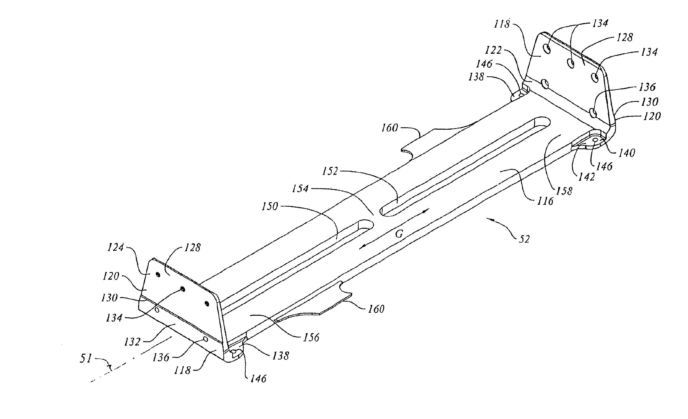
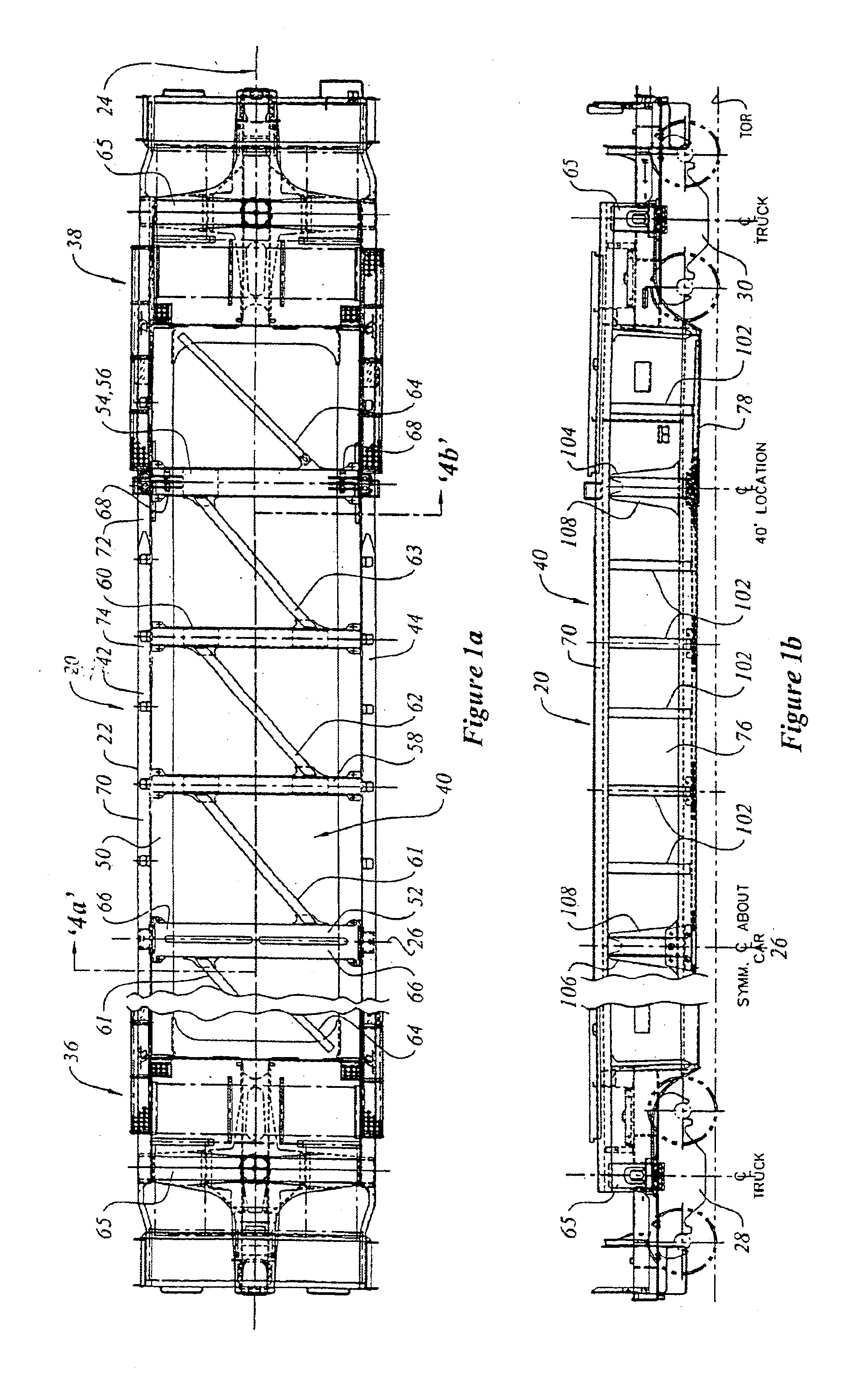
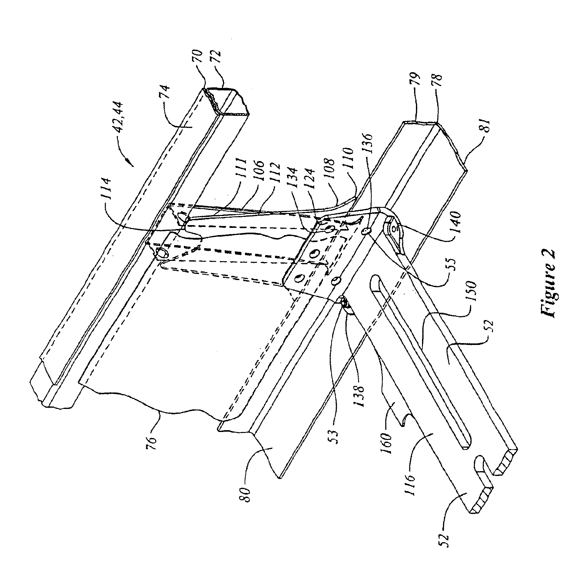
The description that follows, and the embodiments described therein, are provided by way of illustration of an example, or examples, of particular embodiments of the principles of the present invention. These examples are provided for the purposes of explanation, and not of limitation, of those principles and of the invention. In the description, like parts are marked throughout the specification and the drawings with the same respective reference numerals. The drawings are not necessarily to scale and in some instances proportions may have been exaggerated in order more clearly to depict certain features of the invention.

In terms of general orientation and directional nomenclature, for the rail road car described herein, the longitudinal direction is defined as being coincident with the rolling direction of the car, or car unit, when located on tangent (that is, straight) track. The longitudinal direction is parallel to the side sills. Unless otherwise noted, vertical, or upward an...


PUM

PropertyMeasurementUnit
weightaaaaaaaaaa
weightaaaaaaaaaa
lengthsaaaaaaaaaa

Abstract

A well car for carrying shipping containers has a pair of end structures supported by rail car trucks, a pair of first and second spaced apart side beams extending between the end structures and a well defined therebetween. A container support cross member is mounted between the side sills in a position to support an end of a shipping container load carried within the well. The container support cross member may be a monolithic beam member with a attachment fitting formed at an end thereof. The attachment fitting is connectable to a side sill at a moment connection. The remaining end of the cross member is similarly configured and connected to the second side sill. Each end of the cross member has load bearing surface portions which may be used for supporting a corner of a shipping container. The moment connections permit a bending moment to be carried by the cross member between the first and second side sills.

Description

FIELD OF THE INVENTIONThis invention relates to rail road freight cars, and more particularly to a rail road well car having cross members for supporting lading carried in the well car.BACKGROUND OF THE INVENTIONRailway well cars may be conceptualised as having a pair of deep, spaced apart, parallel beams, with floor members extending cross-wise between the beams to form a support frame for lading. The ends of the deep beams are mounted to end structures, and the end structures are supported on a pair of railcar trucks. Although single unit well cars are still common, there has been a trend in recent years toward articulated, multi-unit railcars that permit a relatively larger load to be carried on fewer railcar trucks. The cross section of the car is generally defined by the pair of spaced apart left and right hand deep side beams, and structure between the side sills of the side beams to support such lading as may be placed in the well. Typically the floor, or lading support struc...

Claims


Application Information

Patent Timeline
Patent Type & Authority Patents(United States)
IPC IPC(8): B61D45/00B61D3/00B61D3/20B61F1/00B61F1/10
CPCB61D3/20B61D45/007B61F1/10Y10T29/49996Y10T29/49622Y10T29/49989Y10T29/49995
Inventor KHATTAB, MOHAMED A.
Owner NATIONAL STEEL CAR
Why Eureka
Try Eureka