Composite diaphragm for diaphragm pumps

a diaphragm pump and composite technology, applied in the direction of flexible wall reciprocating engines, mechanical apparatus, pumps, etc., can solve the problems of limiting the useful life of the diaphragm, losing the chemical resistance of the composite diaphragm to aggressive conveying media, etc., and achieve good roll-off properties

Inactive Publication Date: 2005-04-12
ULMAN DICHTUNGSTECHN
View PDF6 Cites 55 Cited by
  • Summary
  • Abstract
  • Description
  • Claims
  • Application Information

AI Technical Summary

Benefits of technology

It is an object of the invention to provide a composite diaphragm for diaphragm pumps that permits a long useful lif

Problems solved by technology

As this damage to the PTFE material progresses, the composite diaphragm loses its chemical resistance to aggre

Method used


Image

  • Composite diaphragm for diaphragm pumps
  • Composite diaphragm for diaphragm pumps
  • Composite diaphragm for diaphragm pumps

Examples


Embodiment Construction

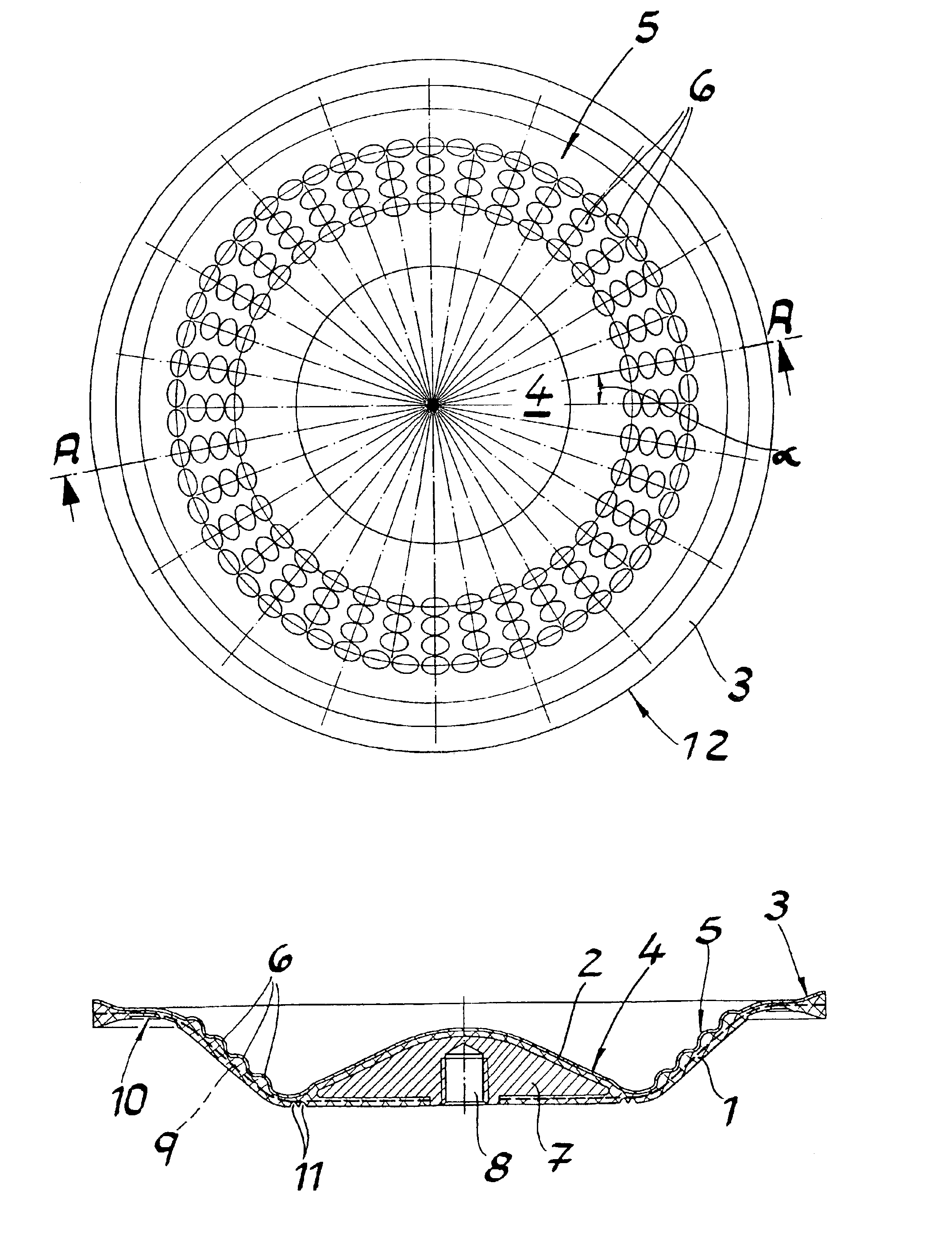
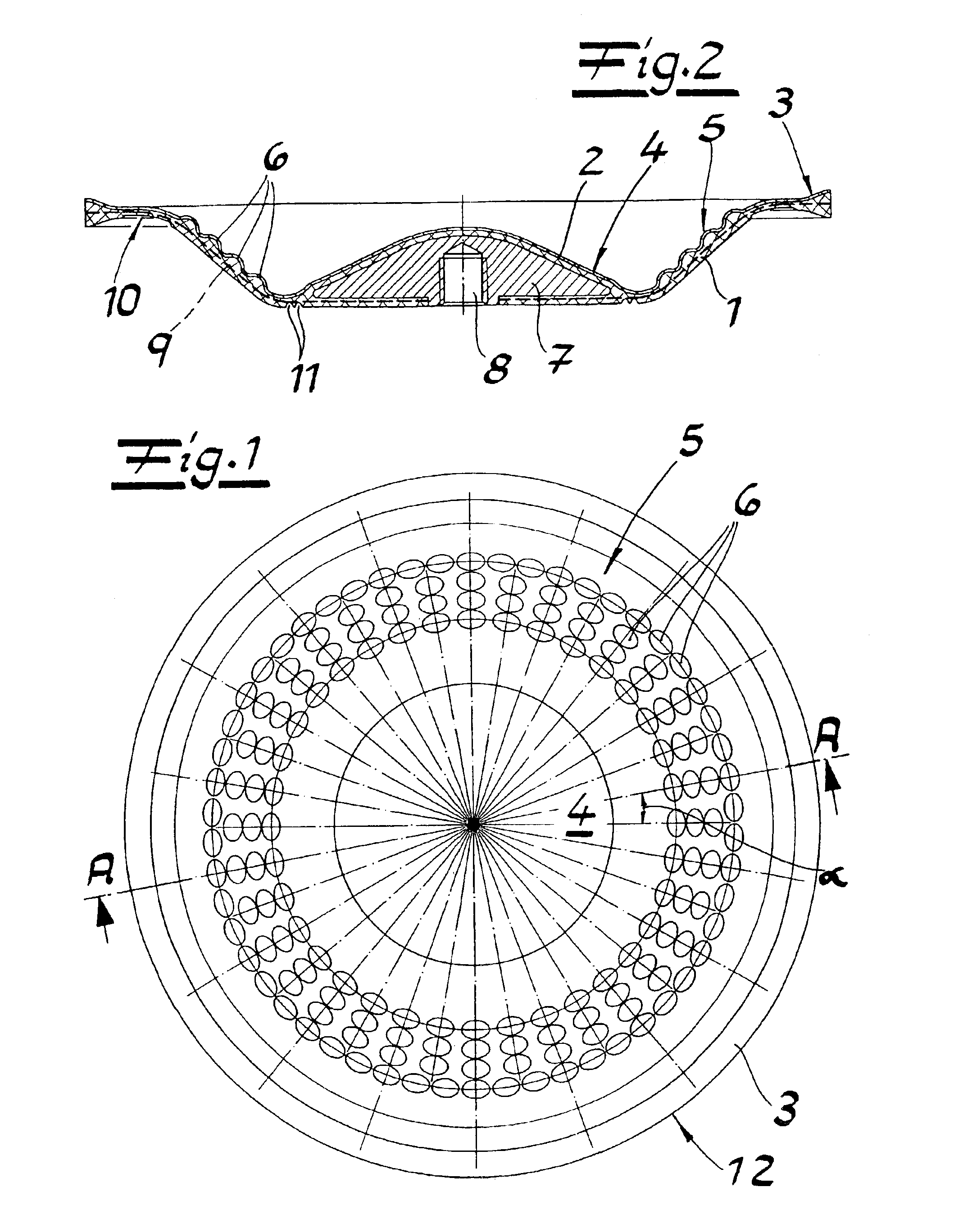
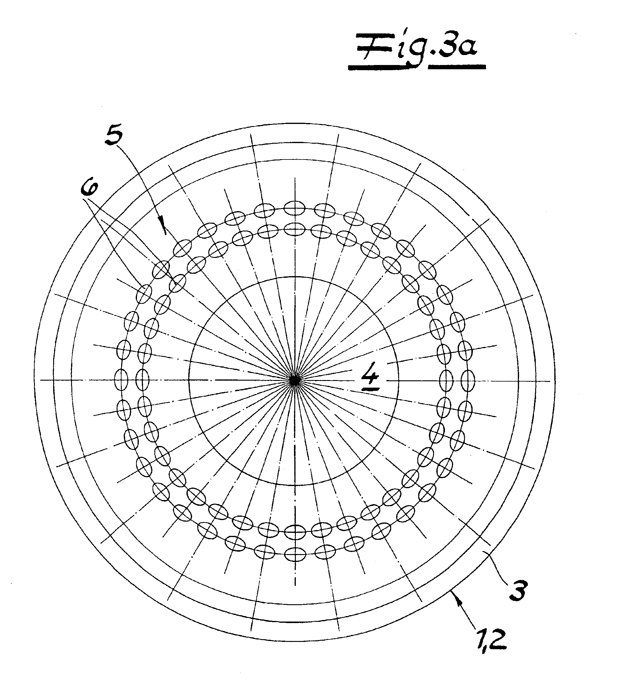
Referring in detail to FIG. 1, the drawings show a composite diaphragm for diaphragm pumps. The composite diaphragm comprises an elastomer body 1 and a coating 2 of polytetrafluoroethylene (PTFE) on the product side. The elastomer body has the shape of a circular dish with an edge 3 of the dish with a clamping area; a bottom 4; and a flexible section 5 of the diaphragm connecting the edge of the dish with the bottom. A comparative look at the figures shows that the flexible section 5 of the diaphragm comprises a multitude of reinforcing elements which can be in the form of naps or protrusions 6 forming elevations in PTFE coating 2. Naps 6 are formed as cups with a preferably circular base area and are arranged in the exemplified embodiments in concentric circles with an angular distribution α of between 5° and 30°.

As in FIG. 1, the naps are arranged so that they are lined up closely spaced in the radial direction in lines extending through the center of the circle. Furthermore, FIG....


PUM

PropertyMeasurementUnit
Angleaaaaaaaaaa
Angleaaaaaaaaaa
Angleaaaaaaaaaa

Abstract

A composite diaphragm for diaphragm pumps comprises an elastomer body and a polytetrafluoroethylene (PFTE) coating on its back side. The elastomer body has a shape of a circular dish that has an edge region with a clamping area, a bottom and a flexible section of the diaphragm that connects the edge of the dish with the bottom. The flexible section of the diaphragm comprises a multitude of naps forming elevations on the coated side of the elastomer body. The PFTE coating is a plane ring surface with the area of the flexible section of the diaphragm.

Description

BACKGROUND OF THE INVENTION1. Field of the InventionThe invention relates to a composite diaphragm for diaphragm pumps comprises of an elastomer body and a polytetrafluoroethylene (PTFE) coating on the product side. This elastomer body has the shape of a circular dish that comprises an edge of the dish with a clamping area; a bottom; and a flexible section of the diaphragm connecting the edge of the dish with the bottom.The composite diaphragm is clamped in a diaphragm pump along the side of the edge, whereas the bottom performs lifting movements. The flexible section of the diaphragm is turned inside out with each lifting movement, whereby roll-off movements of the flexible material are observed in a radial section. Technically speaking, the flexible section of the diaphragm can therefore be referred to as a rolling loop in a tech.2. The Prior ArtWhen composite diaphragms are used, where the flexible section of the diaphragm is a smooth ring surface and where the PTFE coating conta...

Claims


Application Information

Patent Timeline
IPC IPC(8): F04B43/00F16J3/02F16J3/00
CPCF04B43/0054F16J3/02F05C2225/04
Inventor OHRLE, JOACHIMRADOM, LEON
Owner ULMAN DICHTUNGSTECHN
Why Eureka
Try Eureka