Variable valve operating system for internal combustion engine

a technology of internal combustion engine and operating system, which is applied in the direction of valve details, valve arrangements, valve drives, etc., to achieve the effect of suppressing or avoiding engine performance degradation

Active Publication Date: 2005-04-12
NISSAN MOTOR CO LTD
View PDF6 Cites 25 Cited by
  • Summary
  • Abstract
  • Description
  • Claims
  • Application Information

AI Technical Summary

Benefits of technology

[0007]Accordingly, it is an object of the invention to provide a variable valve operating system for an internal combustion engine with a plurality of variable valve timing control mechanisms and a variable valve lift and working angle control mechanism, capable of effectively suppressing or avoiding a degradation in engine performance, such as a lack of engine output torque, from occurring owing to unbalanced valve timings of the variable valve timing control mechanisms functioning properly and improperly, by way of optimal control for respective operating states of the variable valve timing control mechanisms and the variable valve lift and working angle control mechanism functioning properly, even in presence of a variable valve timing control mechanism failure or a variable valve timing control system failure.

Problems solved by technology

When a failure or malfunction of the variable valve timing control mechanism arranged in a first bank of the two cylinder banks is detected, a desired valve timing of the variable valve timing control mechanism arranged in the second bank is forcibly adjusted or brought closer to an actual valve timing of the variable valve timing control mechanism that is arranged in the first bank and fails to function properly.

Method used


Image

  • Variable valve operating system for internal combustion engine
  • Variable valve operating system for internal combustion engine
  • Variable valve operating system for internal combustion engine

Examples


Embodiment Construction

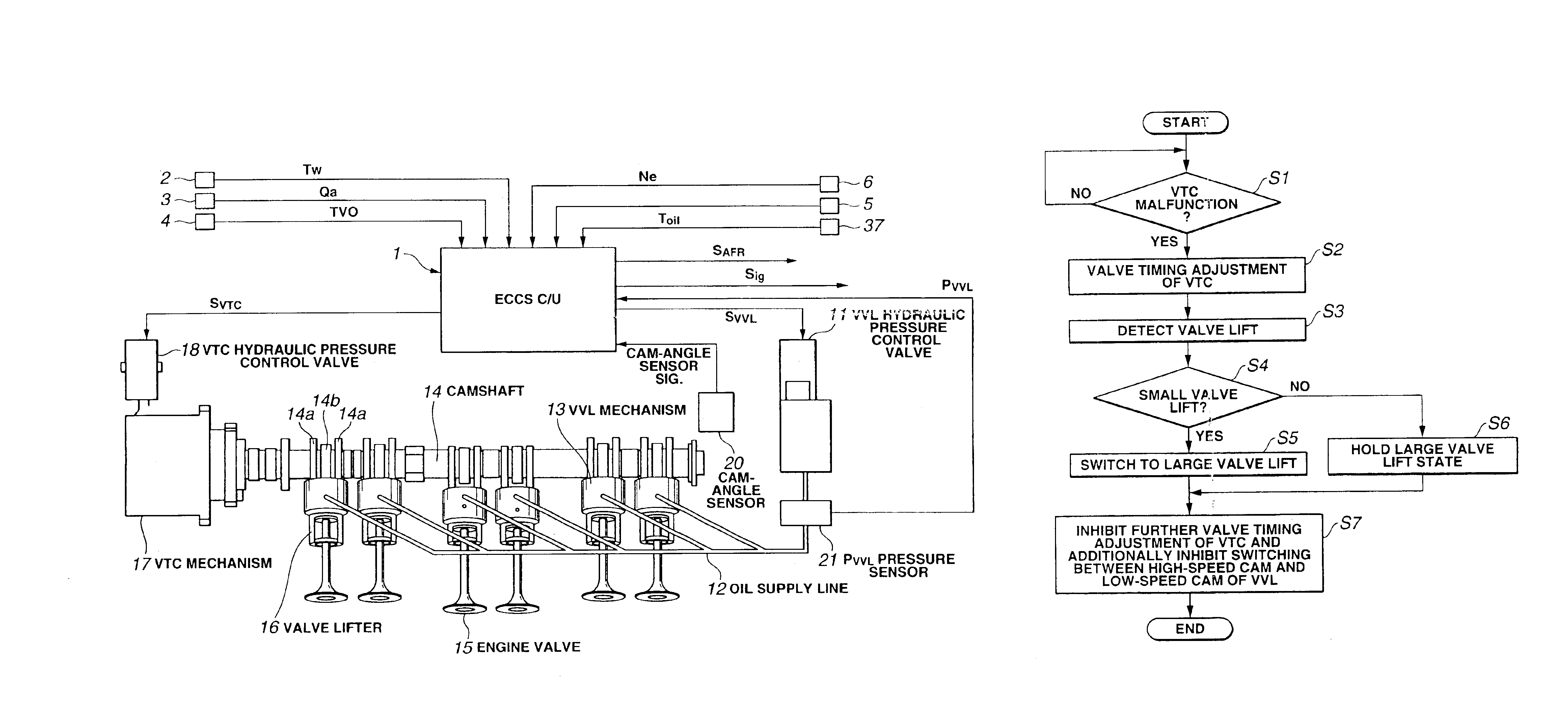
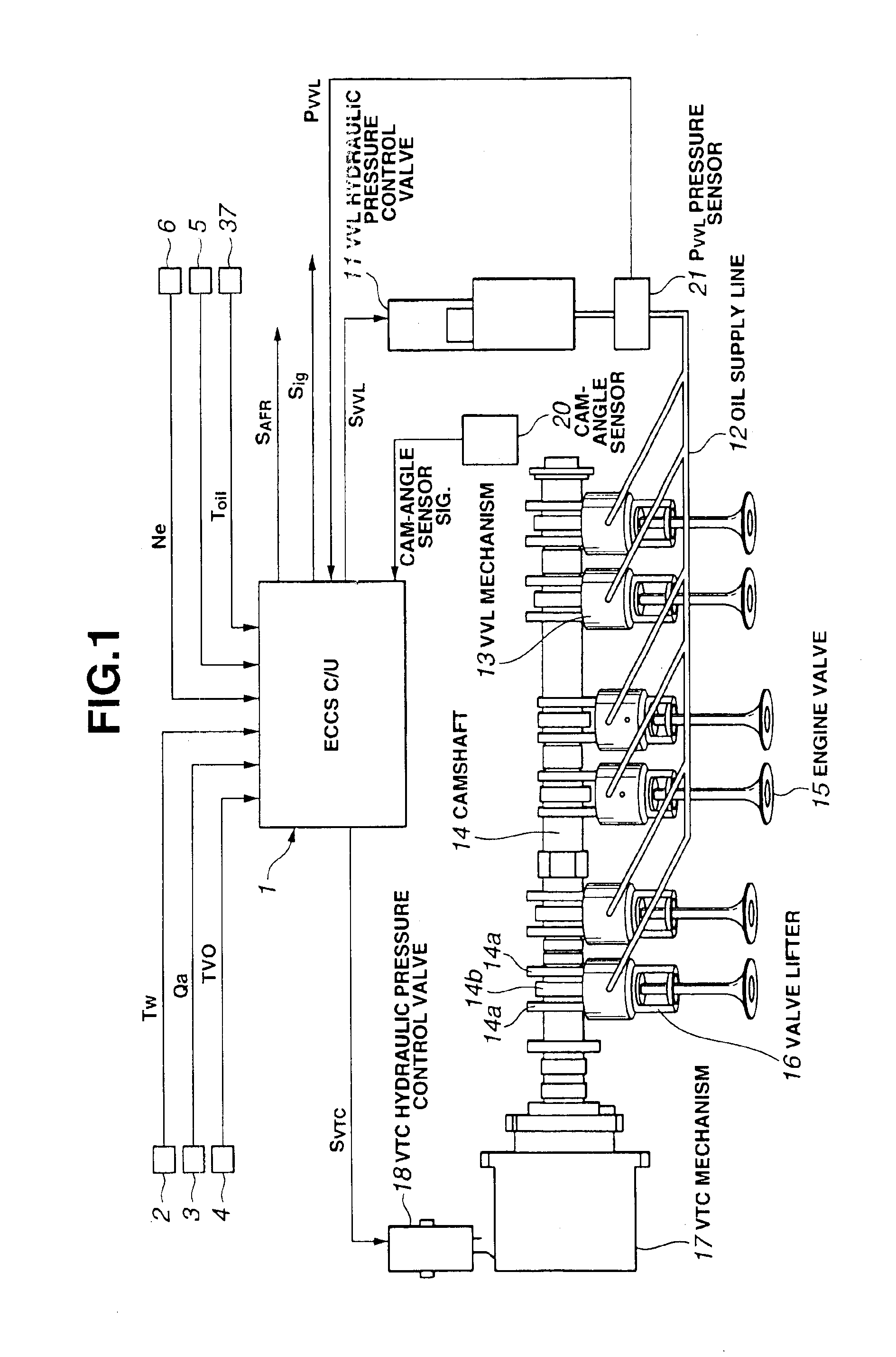
[0024]Referring now to the drawings, particularly to FIG. 1, the variable valve operating system of the embodiment is exemplified in a V-type, double-overhead-camshaft internal combustion engine with two camshafts per cylinder bank.

[0025]As shown in FIG. 1, the variable valve operating system of the embodiment is comprised of a hydraulically-operated variable valve-lift and working-angle control (VVL) mechanism 13 through which a valve lift and a working angle of each of intake valves 15 are both varied, and a plurality of hydraulically-operated variable valve timing control (VTC) mechanisms 17A and 17B, which are collectively referred to as “VTC mechanism 17”, arranged in the respective cylinder banks. VTC mechanism 17 is provided for varying a valve timing of each of intake valves 15. Typical detailed construction of such VVL mechanism 13 has been disclosed, for example, in Japanese Patent Provisional Publication No. 8-177433, whereas typical detailed construction of such VTC mech...


PUM


Abstract

A variable valve operating system for a two-bank engine includes a variable valve-lift and working-angle control mechanism changing at least one of a valve lift and a working angle of each of engine valves arranged in each of cylinder banks, and two variable valve timing control mechanisms provided for each of the banks for changing valve timings independently of each other. A control unit responds a failure in one of the variable valve timing control mechanisms for failsafe purposes. The control unit includes a failsafe section capable of executing a failsafe operating mode in which at least one of the valve lift and the working angle of each of engine valves is increasingly compensated for by the variable valve-lift and working-angle control mechanism, when the one variable valve timing control mechanism is failed.

Description

TECHNICAL FIELD[0002]The present invention relates to a variable valve operating system for an internal combustion engine, and specifically to a fail-safe technology in presence of a failure in a variable valve operating system enabling a variable valve timing control function and a variable valve-lift / working-angle control function.BACKGROUND ART[0003]In recent years, there have been proposed and developed various fail-safe technologies for variable valve timing control systems. One such fail-safe technology has been disclosed in Japanese Patent Provisional Publication No. 5-98916 (hereinafter is referred to as “JP5-98916”).[0004]In the variable valve timing control system disclosed in JP5-98916, two variable valve timing control mechanisms are respectively arranged in two cylinder banks for a V-type internal combustion engine. When a failure or malfunction of the variable valve timing control mechanism arranged in a first bank of the two cylinder banks is detected, a desired valve...

Claims


Application Information

Patent Timeline
Patent Type & Authority Patents(United States)
IPC IPC(8): F02B75/22F01L1/34F01L13/00F02B75/00F02D13/02
CPCF01L1/34F02B75/22F01L13/0036F01L1/024F01L2001/0537F01L2800/00
Inventor SHINDOU, SHIGEKITORIUMI, MASAKITAKAGI, YUSUKE
Owner NISSAN MOTOR CO LTD
Why Eureka
Try Eureka