

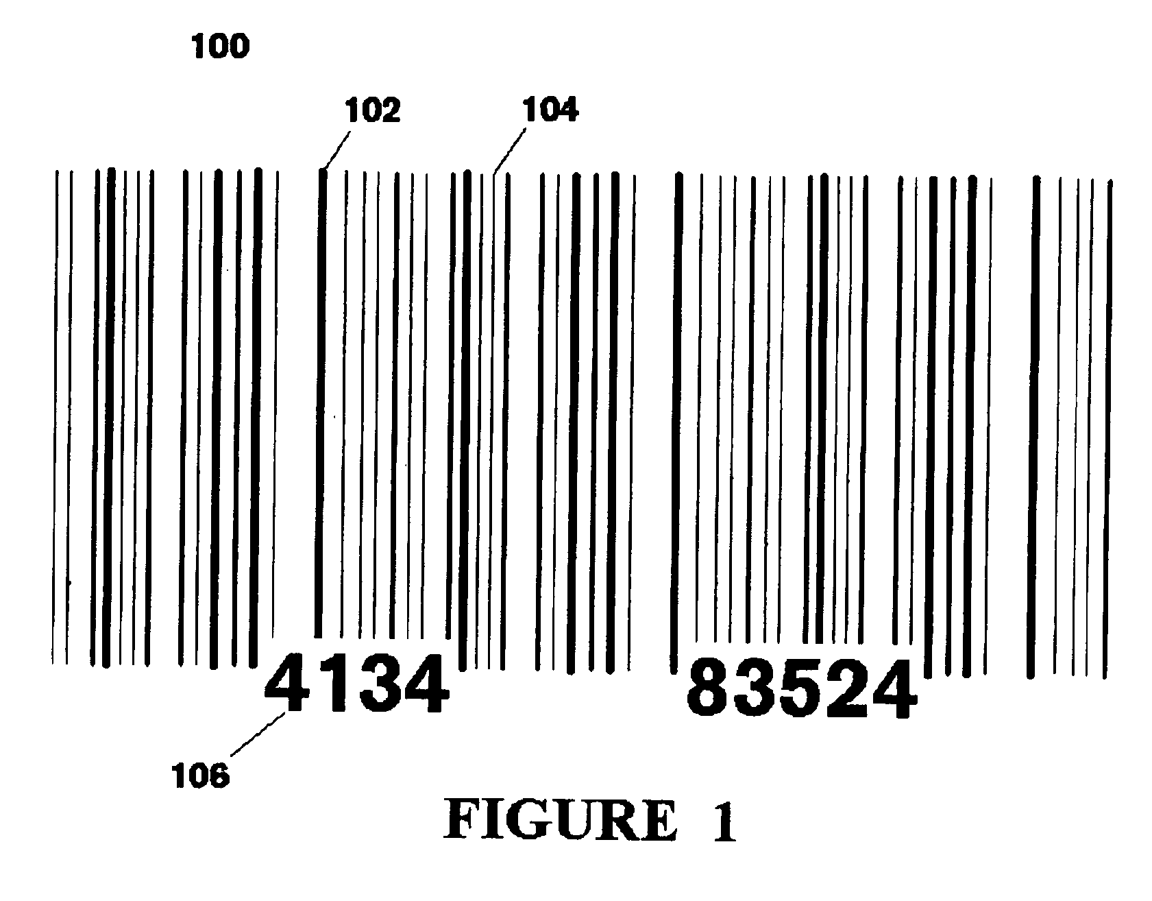
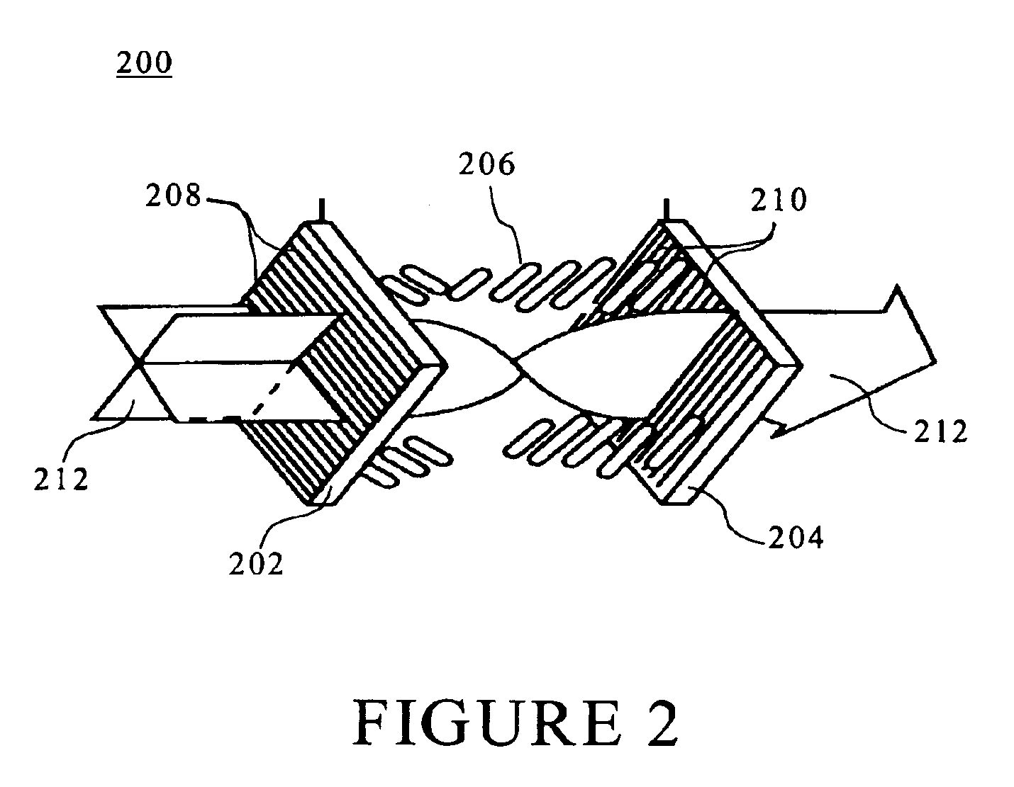
Scannable barcode display and methods for using the same
a barcode display and scanning technology, applied in the field of scanning barcode displays, can solve the problems of changing the light polarization angle, the simplified “point and scan” technology does not work with all display technologies, and the successful capture of information, etc., to facilitate the redemption and/or clearing of electronic coupons, facilitate the use of wireless ticketing systems, and facilitate the effect of electronic coupons
- Summary
- Abstract
- Description
- Claims
- Application Information
AI Technical Summary
Benefits of technology
Problems solved by technology
Method used
Image

Examples
Embodiment Construction
It is to be understood that the figures and descriptions of the present invention have been simplified to illustrate elements that are relevant for a clear understanding of the invention, while eliminating, for purposes of clarity, other elements that may be well known. Those of ordinary skill in the art will recognize that other elements are desirable and / or required in order to implement the present invention. However, because such elements are well known in the art, and because they do not facilitate a better understanding of the present invention, a discussion of such elements is not provided herein. The detailed description will be provided hereinbelow with reference to the attached drawings.
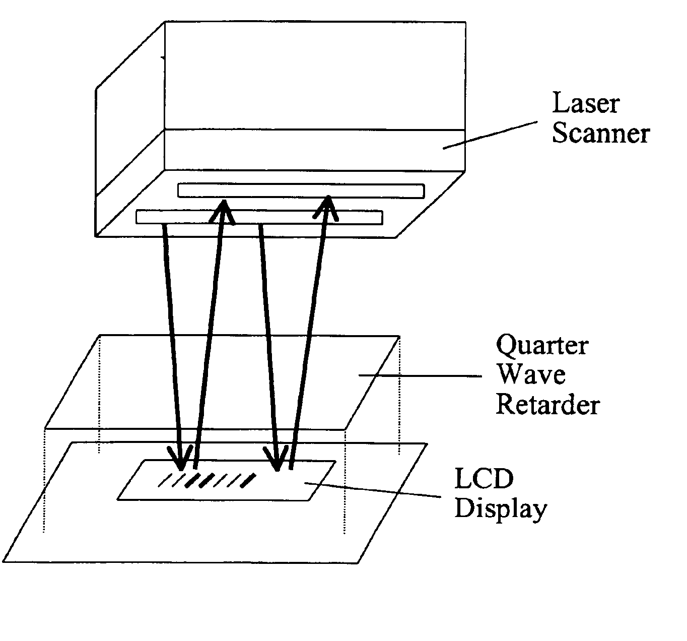
The present invention provides, in at least one preferred embodiment, a system and method for storing, scanning, and redeeming electronic coupons. The system may utilize existing components, such as LCD-based cellular telephones and laser (or other electromagnetic wave-based) scanners to tr...
PUM
 Abstract
Description
Claims
Application Information