Sensor-mirror arrangement on a windshield

a technology of mirrors and sensors, applied in the direction of mirrors, starter details, photoelectric discharge tubes, etc., can solve the problems of unfavorable positioning of sensors alongside mirror mountings, difficult mounting of sensors, etc., and achieve the effect of improving the utilization of mounting space and especially economic realization

Inactive Publication Date: 2005-04-12
CHEMTRON RES
View PDF16 Cites 41 Cited by
  • Summary
  • Abstract
  • Description
  • Claims
  • Application Information

AI Technical Summary

Benefits of technology

The present invention deals with the problem of disclosing an improved design for a sensor-mirror of the type mentioned at the beginning, which in particular makes possible a better utilization of the mounting space.
The invention is based on the general idea of placing the first fastening element of the mirror mounting at a distance from the windshield using a pedestal when moving the mirror mounting along the windshield. In this way, it is possible to correct the spatial bearing with an inside rear view mirror that leaves the prescribed angle of view geometry when moved upward so that the inside rear view mirror once again possesses the necessary angle of view geometry. In this way, it is possible, with restricted available space, to arrange the sensor below the mirror mounting on the windshield. Because this structure can use a typical, standard inside view mirror, conversion from an outfitting variant without sensor to an outfitting variant without a sensor can be especially economically realized. In particular, reconstruction of the inside rear view mirror is not necessary.

Problems solved by technology

The installation of a sensor can be problematic if the sensor gets into the free field of vision when installed beneath the standard position of the mirror mounting and moves out of the wiping field when installed above the mass production arrangement, and a positioning of the sensor alongside the mirror mounting is not desired.

Method used


Image

  • Sensor-mirror arrangement on a windshield
  • Sensor-mirror arrangement on a windshield
  • Sensor-mirror arrangement on a windshield

Examples


Embodiment Construction

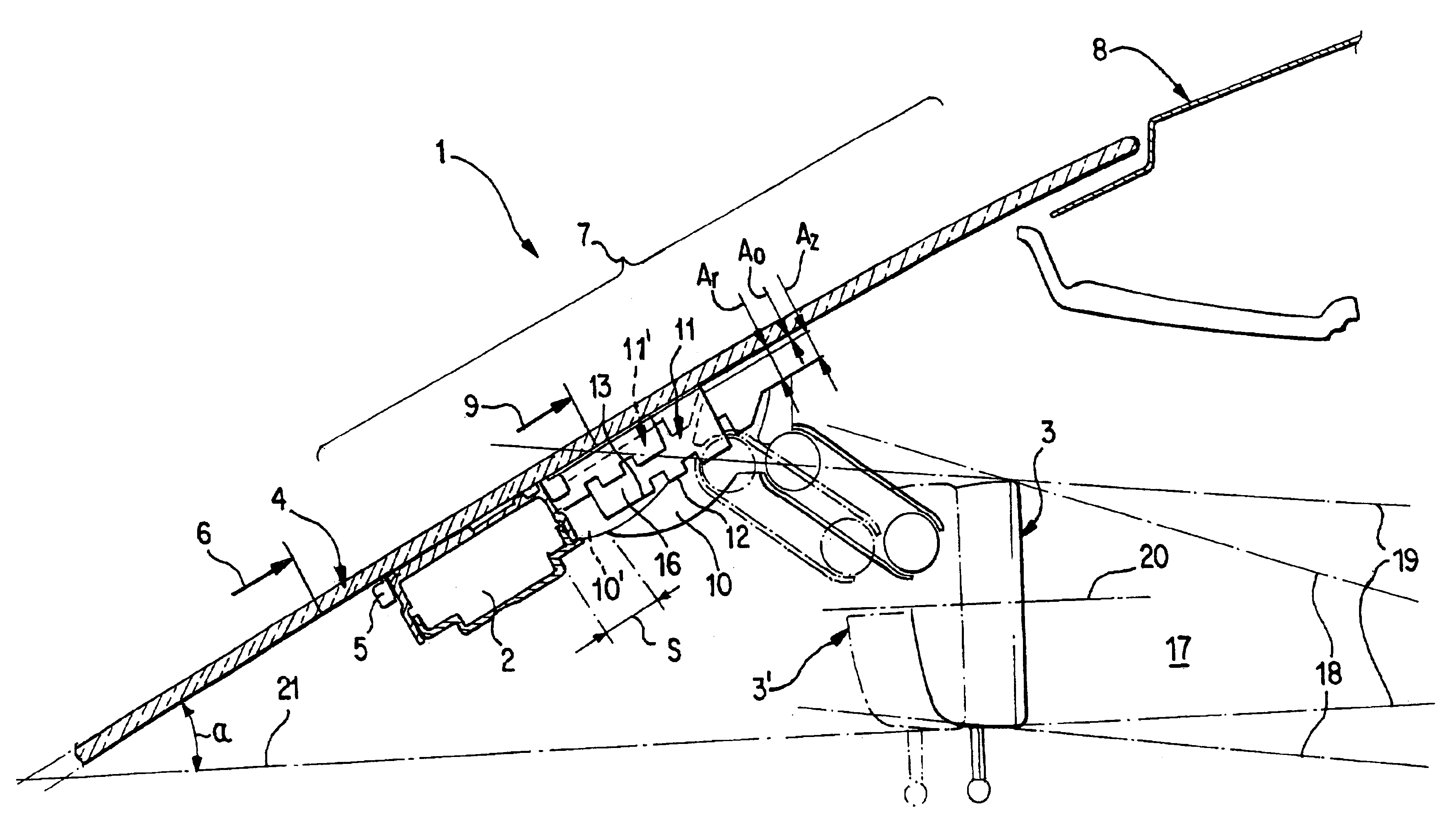
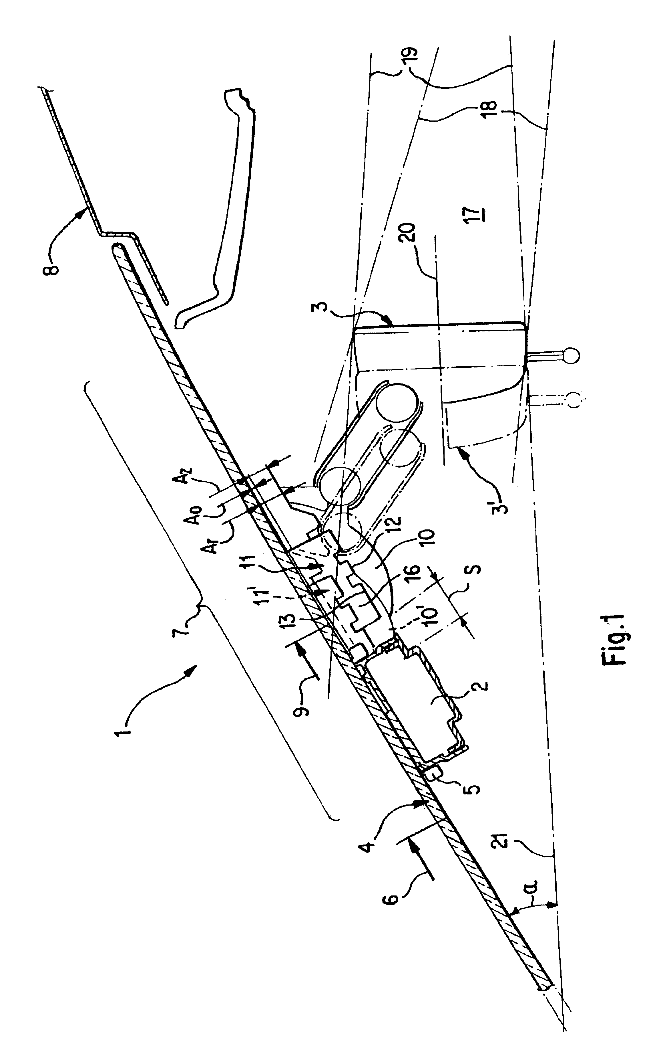
Corresponding to FIG. 1, a sensor-mirror arrangement 1 of the invention includes at least one optical sensor 2 and an inside rear view mirror 3. The sensor 2 can be, for example, a rain and / or light sensor that is mounted on the windshield 4 of a motor vehicle, especially a passenger car, to fulfill its function. For this purpose, the arrangement 1 includes a sensor mounting 5 which serves for positioning and fixation of the sensor 2.

The windshield 4 possesses a visual field 6 the upper limit of which is marked in FIG. 1 by an arrow. No obstructing impediment may be arranged in this visual field 6, and inside rear view mirrors 3 may not be fastened to the windshield 4 inside this visual field 6. An upper edge region 7 joins above this field of vision 6 which in FIG. 1 is characterized by a brace and extends up to a motor vehicle roof 8. A windshield wiper device (not depicted) allocated to the windshield 4 possesses a wiping area 9 the upper boundary of which is marked in the sectio...


PUM


Abstract

A sensor-mirror arrangement on a windshield of a motor vehicle with an optical sensor that is fastened on the windshield in an edge region arranged between a free field of vision of the windshield and vehicle roof, and with an inside rearview mirror that is fastened using a mirror mounting in an upper edge region between the sensor and the vehicle roof. The mirror mounting has a first fastening element that interacts with a complementary second fastening element for fastening the inside rearview mirror, which is constructed with a mirror base of the inside rearview mirror. The mirror mounting moreover has a pedestal fastened on the windshield on its side facing away from the windshield the first fastening element is formed. The pedestal is dimensioned so that the mirror base fastened to the mirror holding has a predetermined distance from the windshield, which is greater that a minimum distance if need be required for the installation and / or function of the mirror base.

Description

BACKGROUND AND SUMMARY OF THE INVENTIONThis application claims the priority of 102 11 443.9, filed Mar. 15, 2002, the disclosure of which is expressly incorporated by reference herein.The present invention concerns a sensor-mirror arrangement on a windshield of a motor vehicle.Installing a rain sensor on a windshield of a motor vehicle with the aid of which a windshield wiper device can be controlled is known from German Reference DE 198 46 969 A1. In order to be able to control wiper activity as needed with the help of the rain sensor, it is necessary to arrange the rain sensor on the windshield inside the wiping field of the windshield wiper device. Moreover, legal provisions must be observed that prohibit positioning a visual obstruction within a prescribed field of vision of the windshield. Correspondingly, a rain sensor of this type can be positioned, for example, in an upper edge region of the windshield that is situated between the free field of vision and a roof of the motor...

Claims


Application Information

Patent Timeline
Patent Type & Authority Patents(United States)
IPC IPC(8): B60R1/02B60R1/04B60R1/12
CPCB60R1/04B60R2001/1223
Inventor KRUG, MARTIN
Owner CHEMTRON RES
Why Eureka
Try Eureka