
Connector apparatus for a medical device

a medical device and connector technology, applied in the field of medical devices, can solve the problems of high manufacturing cost of connector assemblies, limited detail of inability to machine the amount of detail on the sealing surface of each connector block, so as to achieve the effect of greatly reducing the weight of the connector block assembly

Inactive Publication Date: 2005-04-12
BEHAN EDGAR G
View PDF7 Cites 113 Cited by
  • Summary
  • Abstract
  • Description
  • Claims
  • Application Information

AI Technical Summary

Benefits of technology

One advantage of the invention is that the weight of the connector block assembly is greatly reduced as compared with present connector block assemblies.
is that the weight of the connector block assembly is greatly reduced as compared with present connector block assemblies.
Another advantage of the invention is that the housings of the individual connector blocks can be formed by injection molding as compared to presently machined connector blocks.
Another advantage of the invention is that the tab provides a large planar welding surface to which feedthrough wires from a medical device can be connected to the connector block assembly.
Another advantage of the invention is that each connector block is modularized so that potentially infinite connector blocks can be connected in series.

Problems solved by technology

Manufacturing connector assemblies is expensive.
Machining these materials has limitations.
One limitation is the amount of detail capable of being machined on the sealing surface of each connector block.
These preformed cavities frequently have thin walls that are susceptible to damage.
Further, titanium, stainless steel and more exotic material connector blocks can result in a relatively heavy connector assembly.
Heavy assemblies are not desirable.

Method used


Image

  • Connector apparatus for a medical device
  • Connector apparatus for a medical device
  • Connector apparatus for a medical device

Examples


Embodiment Construction

The embodiments described herein provide a novel apparatus and method for the manufacture of a header, or connector top assembly and connector block assembly for use in a variety of medical applications. The particular embodiments are described below for exemplary purposes only, those skilled in the art will understand how to apply the present invention to the proximal connectors of variety of electrode bodies. Therefore, the appended claims are not intended to be limited to any specific example or embodiment described herein. Further, in the drawings described below, reference numerals are generally repeated where identical or similar elements appear in more than one figure.

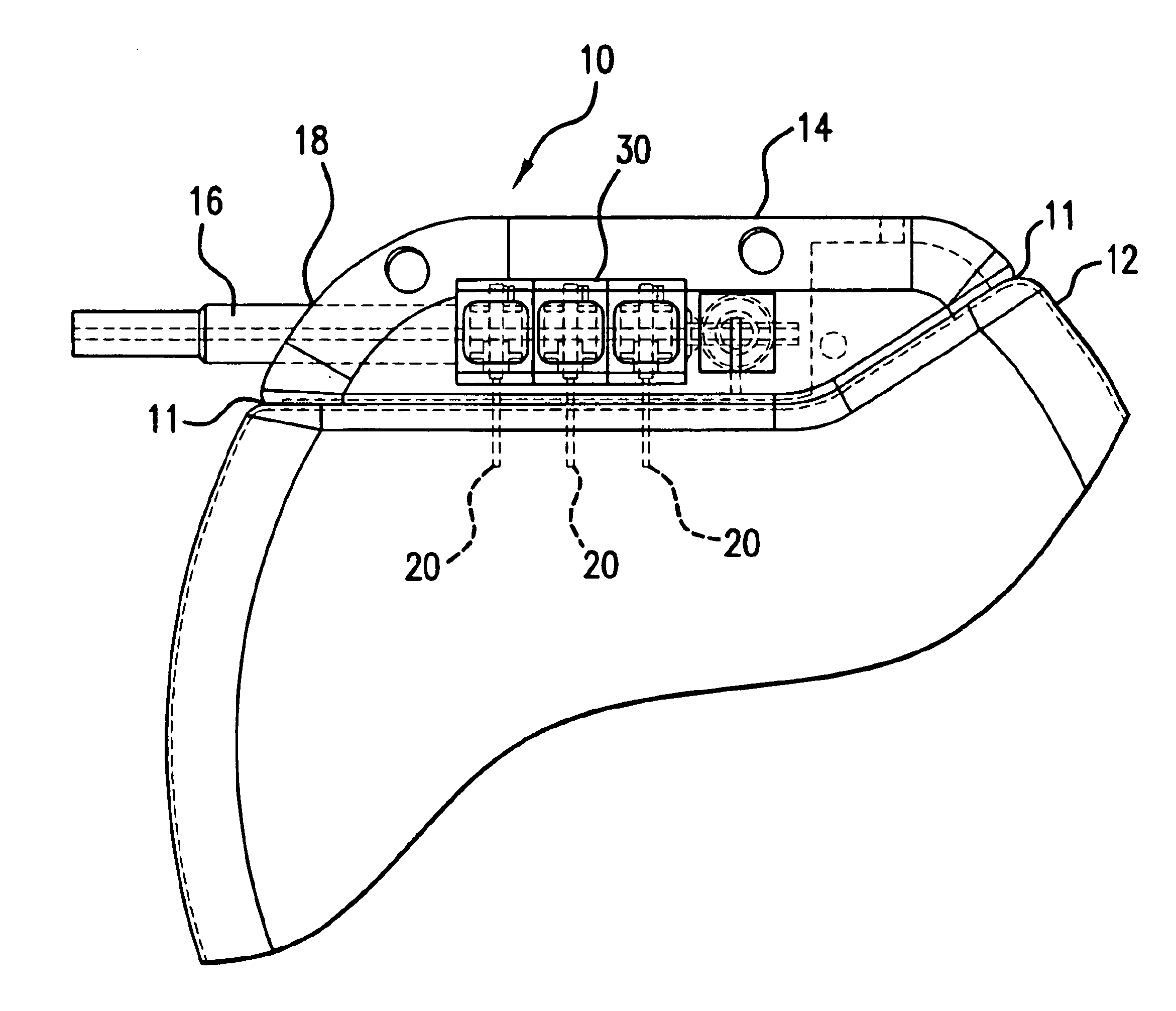
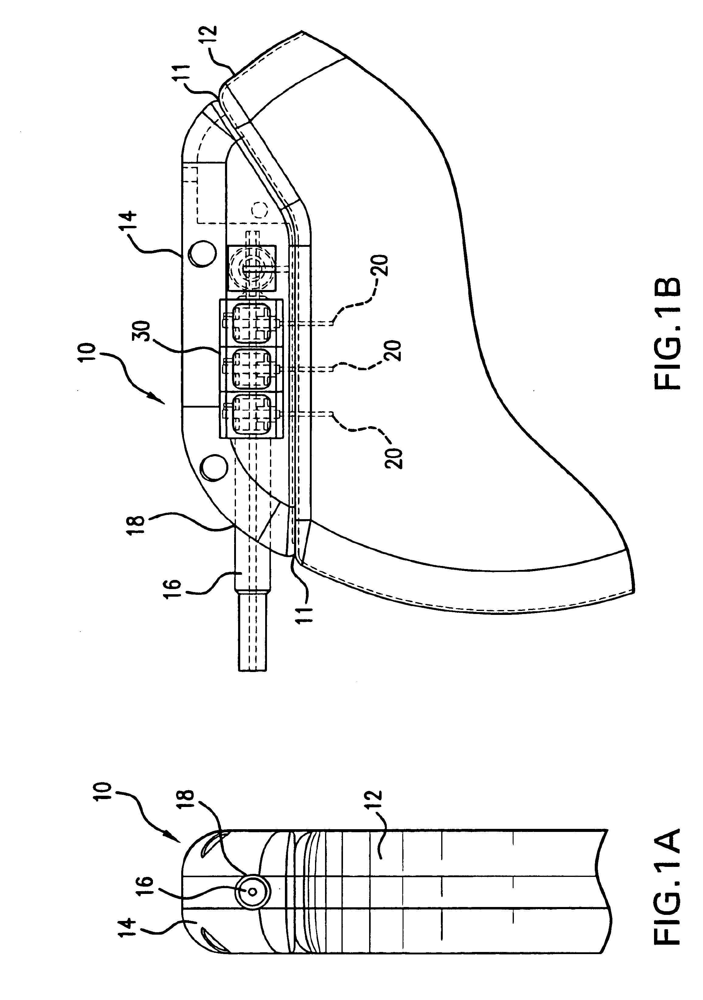
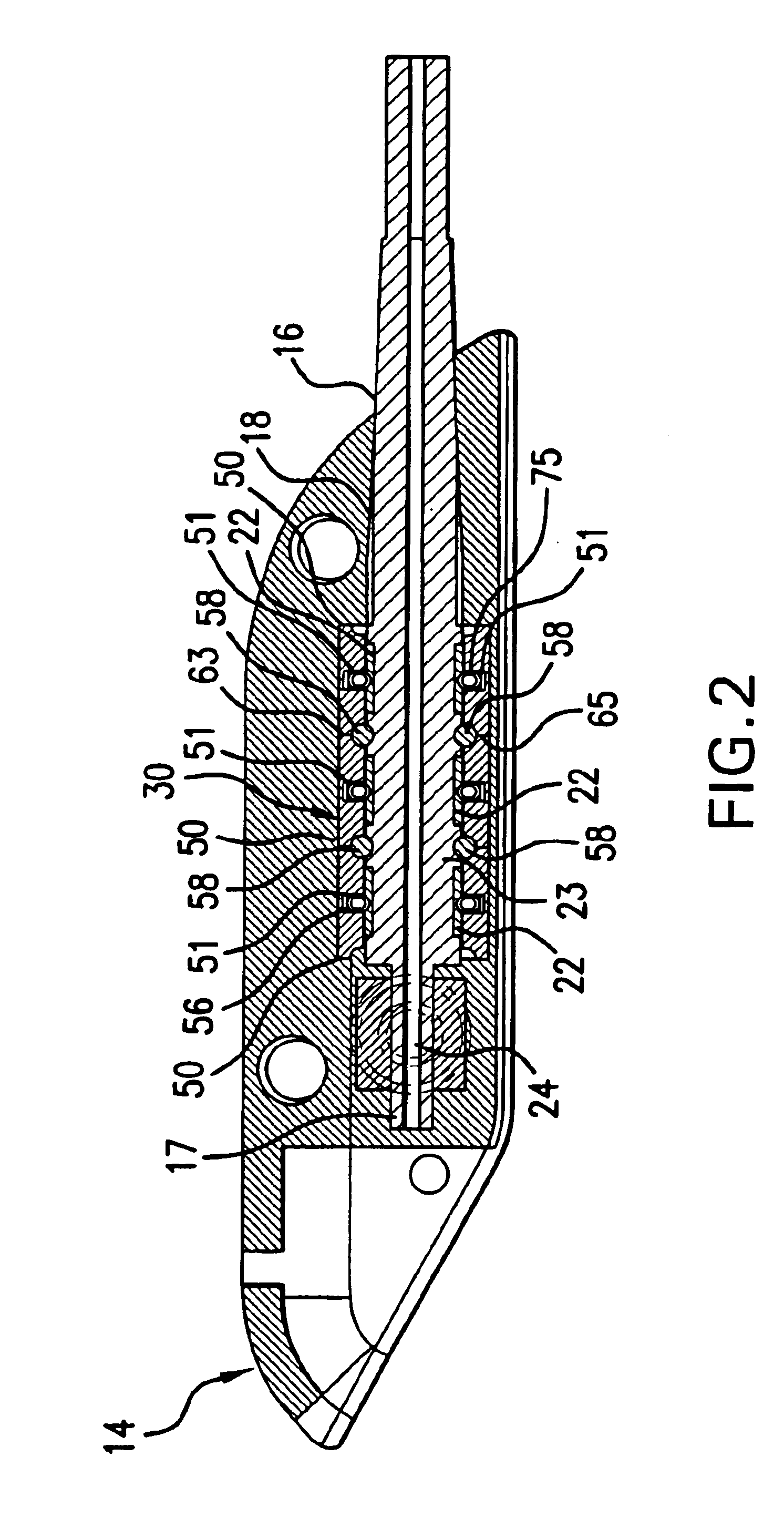
Referring to the drawings wherein like reference numerals designate corresponding parts throughout the several figures, reference is made first to FIGS. 1A and 1B that generally illustrate a medical device 10 in accordance with the present invention. Medical device 10 includes a housing or otherwise hermetic enc...


PUM


Abstract

A connector block assembly for an implantable medical device is described. The connector block generally includes a first and second housing connected to one another forming an indentation that holds a tab. A canted spring or any other electrically conductive displacable configuration is further held within the indentation. The connector block assembly is adapted to be placed within a header, or connector top assembly for an implantable medical device. The tab can be connected to feedthrough wires from the internal circuitry within the medical device. The connector block assembly can interface with a medical electrode to connect a patient's tissue with the medical device.

Description

BACKGROUNDI. Field of the InventionThe present invention relates to medical devices and, more particularly, to a connector assembly for an implantable medical device.II. Description of the Related ArtImplantable medical devices are frequently used to generate an electrical stimulus that is transferred to a target tissue. These devices may also be used to sense electrical signals generated from the target tissues or generated by sensors located at a target location. Some examples of such devices include neurostimulation devices, pacemakers, anti-tachycardia pacers, and defibrillators. Neurostimulation devices are frequently used to artificially stimulate nerves to relieve pain and to treat various neurological disorders whereas pacemakers, anti-tachycardia pacers, and defibrillators are used to stimulate cardiac tissue with an electrical signal in order to correct or modify the rhythm of the heart. Implantable devices generally include a housing which typically hermetically encloses ...

Claims


Application Information

Patent Timeline
IPC IPC(8): H01R24/04H01R24/00H01R24/58
CPCA61N1/3752H01R13/187H01R24/58H01R13/111H01R2105/00Y10S439/909
Inventor BEHAN, EDGAR G.
Owner BEHAN EDGAR G
Learn More