
Ultrasonic diagnostic device

a diagnostic device and ultrasonic technology, applied in ultrasonic/sonic/infrasonic diagnostics, instruments, applications, etc., can solve the problems of complex and tedious setting operation for operators, and achieve the effect of easy observation of overflowing portions and easy estimation of influences

Inactive Publication Date: 2005-04-12
ALOKA CO LTD
View PDF15 Cites 14 Cited by
  • Summary
  • Abstract
  • Description
  • Claims
  • Application Information

AI Technical Summary

Benefits of technology

"The present invention provides an ultrasonic diagnostic device that simplifies the process of setting a region of interest within a three-dimensional space containing a target tissue. The device calculates shape parameters from volume data and sets a plurality of reference lines based on the shape parameters and the position of the target tissue. The device also allows the user to set the reference lines based on plane images displayed on a display. The technical effect of the invention is to simplify the process of setting a region of interest within a three-dimensional space, making it easier for users to diagnose target tissues."

Problems solved by technology

The setting of an ROI in three-dimensional ultrasonic diagnostic devices, however, requires setting of the three-dimensional shape of the ROI and setting of the position of the ROI within a three-dimensional space, and, thus, the setting operation is both complex and tedious for the operator.

Method used


Image

  • Ultrasonic diagnostic device
  • Ultrasonic diagnostic device
  • Ultrasonic diagnostic device

Examples


Embodiment Construction

A preferred embodiment of the present invention will now be described referring to the drawings.

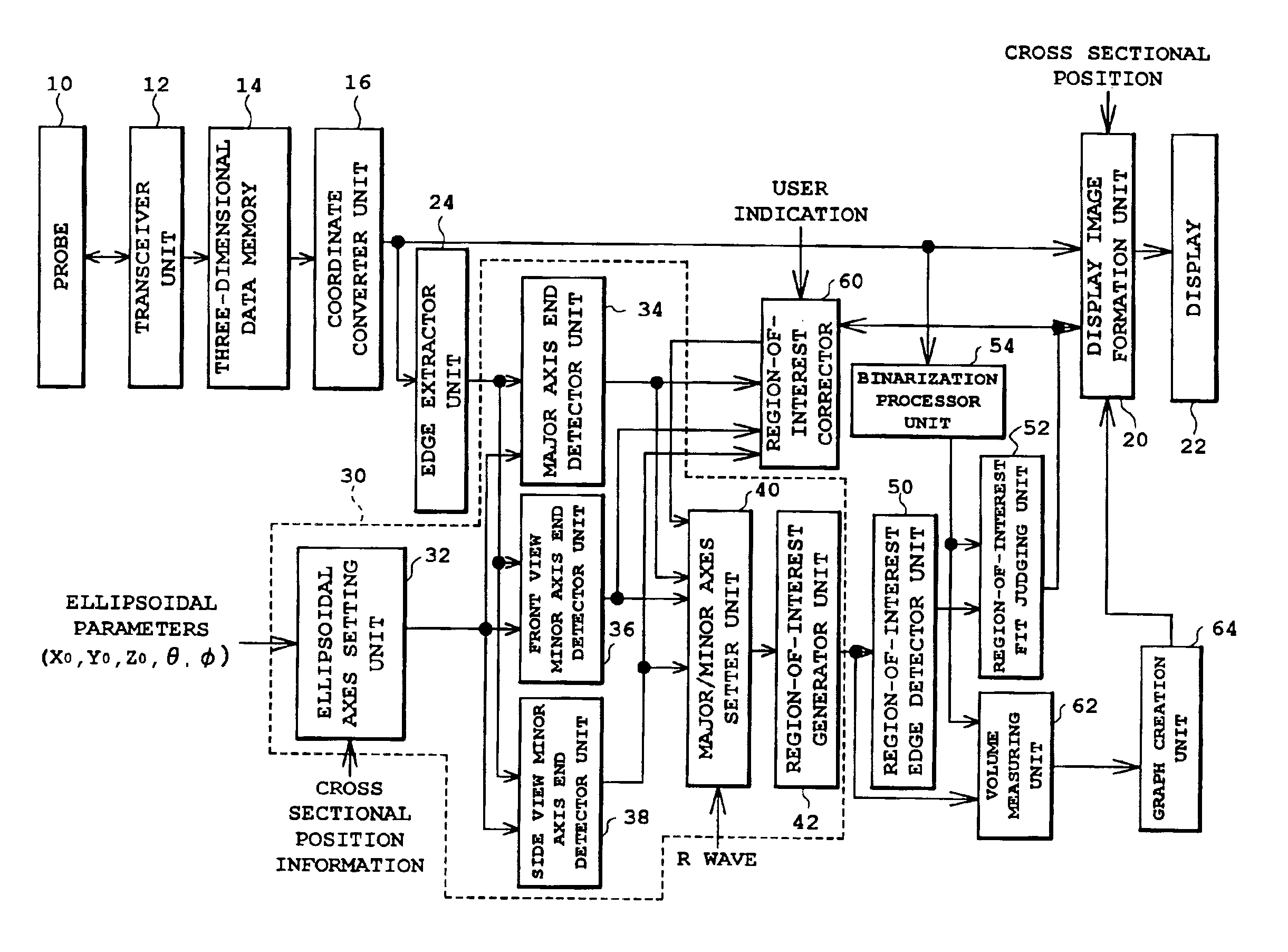
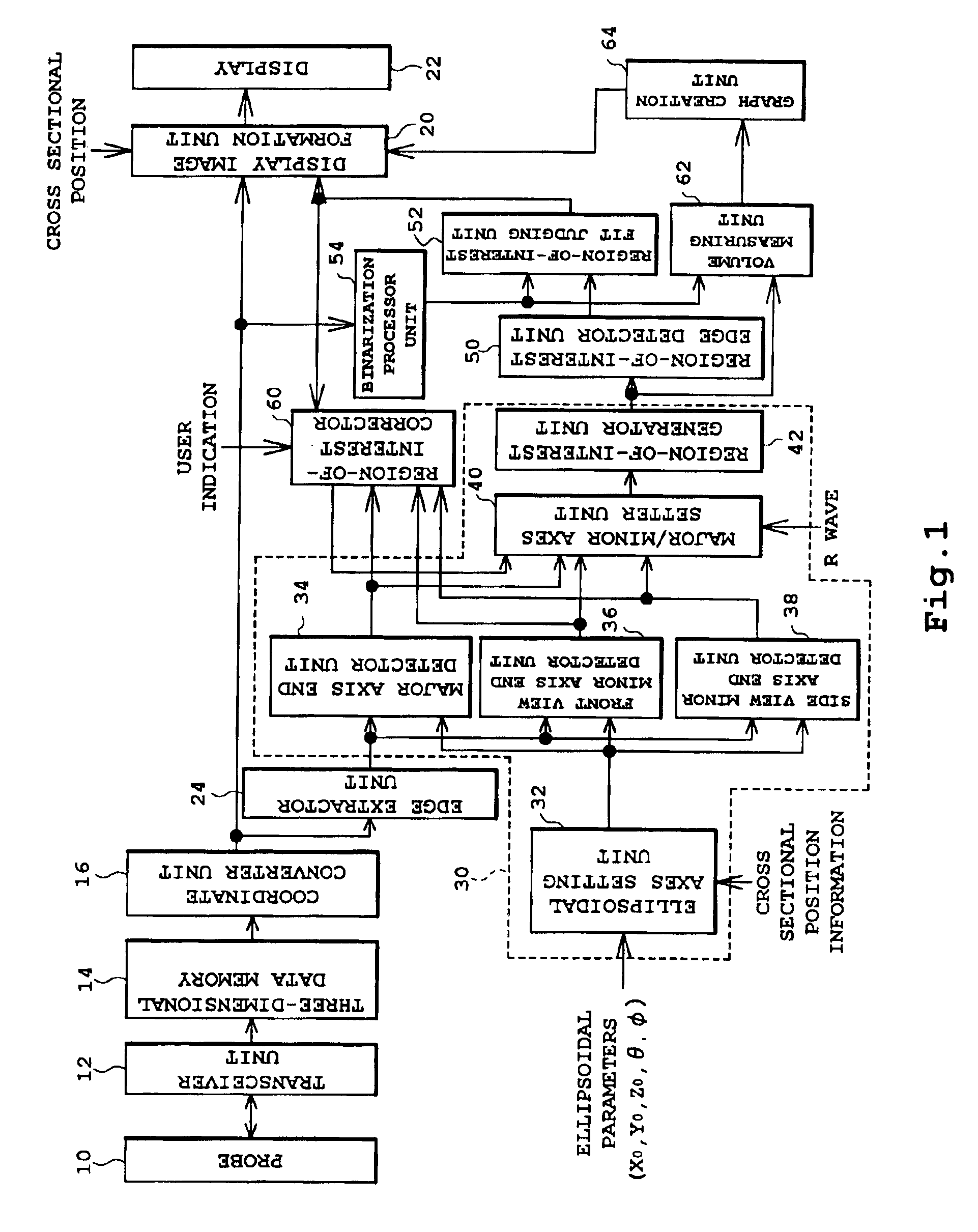
FIG. 1 is a block diagram showing an overall structure of an ultrasonic diagnostic device according to the preferred embodiment of the present invention.

A transceiver unit 12 transmits and receives an ultrasound via a probe 10 into and from a space containing a target tissue to output a three-dimensional ultrasonic image for each time phase to a three-dimensional data memory 14. The three-dimensional ultrasonic image obtained for each time phase is converted, by a coordinate converter unit 16, into a display coordinate system and is output to a display image formation unit 20 and edge extractor unit 24 for each time phase.

The display image formation unit 20 forms a projected image of the three-dimensional ultrasonic image projected on a two-dimensional plane based on the three-dimensional ultrasonic image output from the coordinate converter unit 16 and having converted coordinates. The f...


PUM


Abstract

An ellipsoidal axes setting unit sets major and minor axis of an ellipsoid based on cross sectional position information and ellipsoidal parameters input by a user while viewing a display. A major axis end detector unit, a front view minor axis end detector unit, and a side view minor axis end detector unit detect ends of the major and minor axes based on the major and minor axes set at the ellipsoidal axes setting unit and a target tissue surface image for each time phase output from an edge extractor unit. A major / minor axes setting unit selects appropriate lengths of the major and minor axes from the input ends of the major and minor axes and outputs the selected lengths to a region-of-interest generator unit where a three-dimensional region of interest is generated.

Description

BACKGROUND OF THE INVENTION1. Field of the InventionThe present invention relates to an ultrasonic diagnostic device and in particular to a three-dimensional ultrasonic diagnostic device in which a region of interest (hereinafter also referred to as “ROI”) can be set.2. Description of the Related ArtIn two-dimensional ultrasonic diagnostic devices, the ability to diagnose a target site has been improved by inclusion of a feature allowing the selection of a region of interest (“ROI”). For example, calculation time can been shortened by performing a Doppler calculation for forming a color Doppler image in a selected ROI, while calculation precision can be improved by using only the ROI as the calculation target when an area of a target tissue is to be calculated. The ROI is also employed in three-dimensional ultrasonic diagnostic devices for shortening the calculation time and improving precision of calculation of area or volume (refer to, for example, Japanese Patent Laid-Open Public...

Claims


Application Information

Patent Timeline
Patent Type & Authority Patents(United States)
IPC IPC(8): A61B8/00G01S15/89G01S15/00G01S7/52G06T1/00
CPCA61B8/00A61B8/483G01S15/8993G01S7/5205Y10S128/916
Inventor MURASHITA, MASARU
Owner ALOKA CO LTD
Learn More