
Devices and housings for test sample preparation

a technology for test samples and housings, applied in the direction of biological material analysis, chemical analysis using titration, after-treatment of biomass, etc., can solve the problems of sample loss, time-consuming sequentially, and risk of contamination, and achieve the effect of reducing cross-contamination

Inactive Publication Date: 2005-04-12
PALL CORP
View PDF15 Cites 25 Cited by
  • Summary
  • Abstract
  • Description
  • Claims
  • Application Information

AI Technical Summary

Benefits of technology

The invention is a device for preparing multiple samples for automated liquid chromatography. It includes a housing with a vacuum channel and a filter assembly with a plurality of wells and porous media. The device also includes a sampler tray with vials in liquid receiving relationship with the wells. A key mechanism is coupled to the housing to uniquely define the position of each vial. The device allows for simultaneous preparation of multiple samples and minimizes cross-contamination. It is suitable for automated liquid chromatography and is easy to use with multiple samples.

Problems solved by technology

There are a number of disadvantages associated with the conventional methods of preparing multiple test samples.
For example, it is time-consuming to sequentially filter test samples and deposit them into vials, to transfer filtered test samples from wells to vials, or to transfer vials from a rack to a sampler tray.
Additionally, sample losses occur when test samples are transferred from wells to vials.
Further, there is a risk of contamination during the transfer of test samples from wells to vials and during the transfer of vials from a rack to a sampler tray.

Method used


Image

  • Devices and housings for test sample preparation
  • Devices and housings for test sample preparation
  • Devices and housings for test sample preparation

Examples


Embodiment Construction

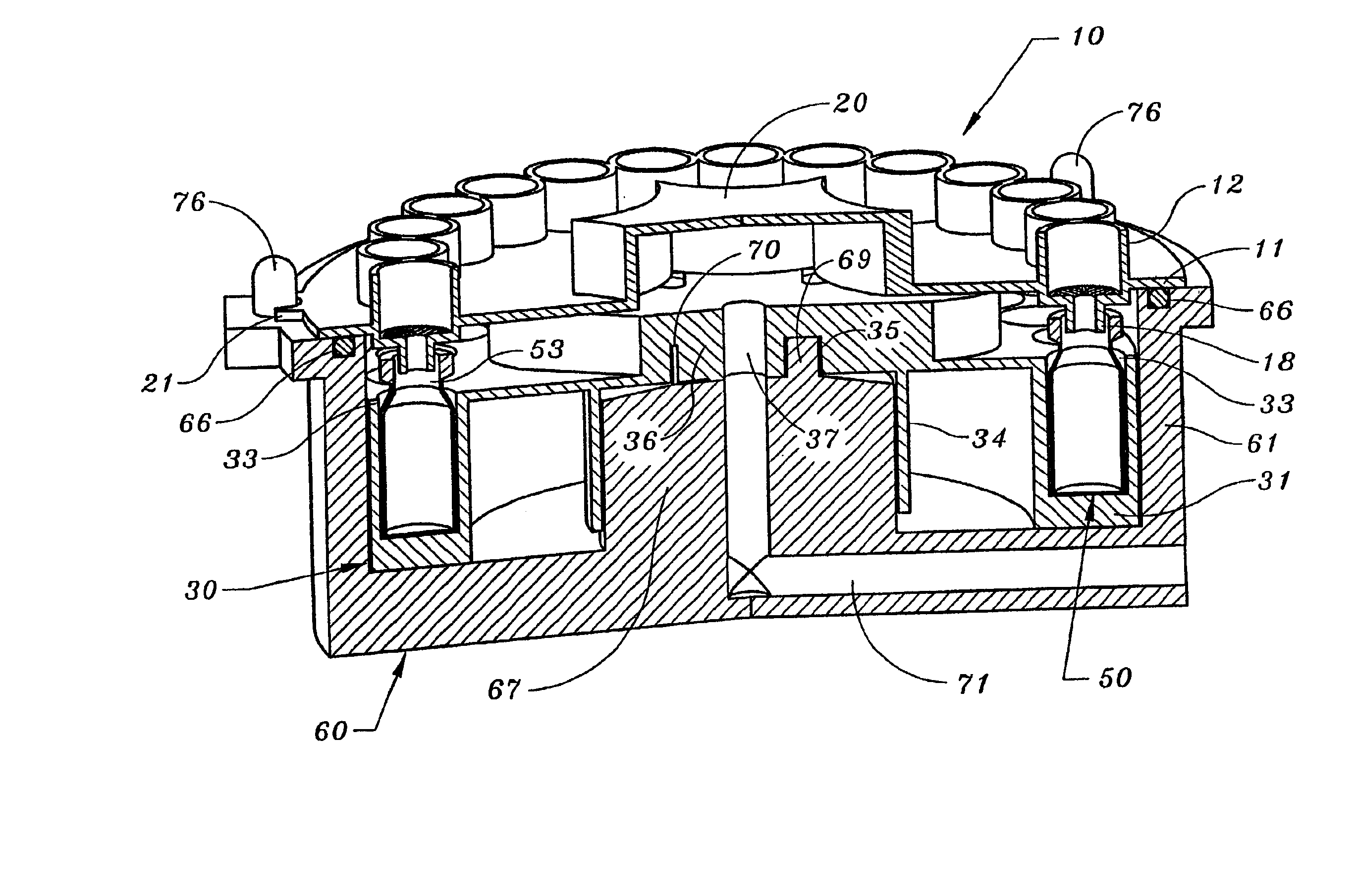
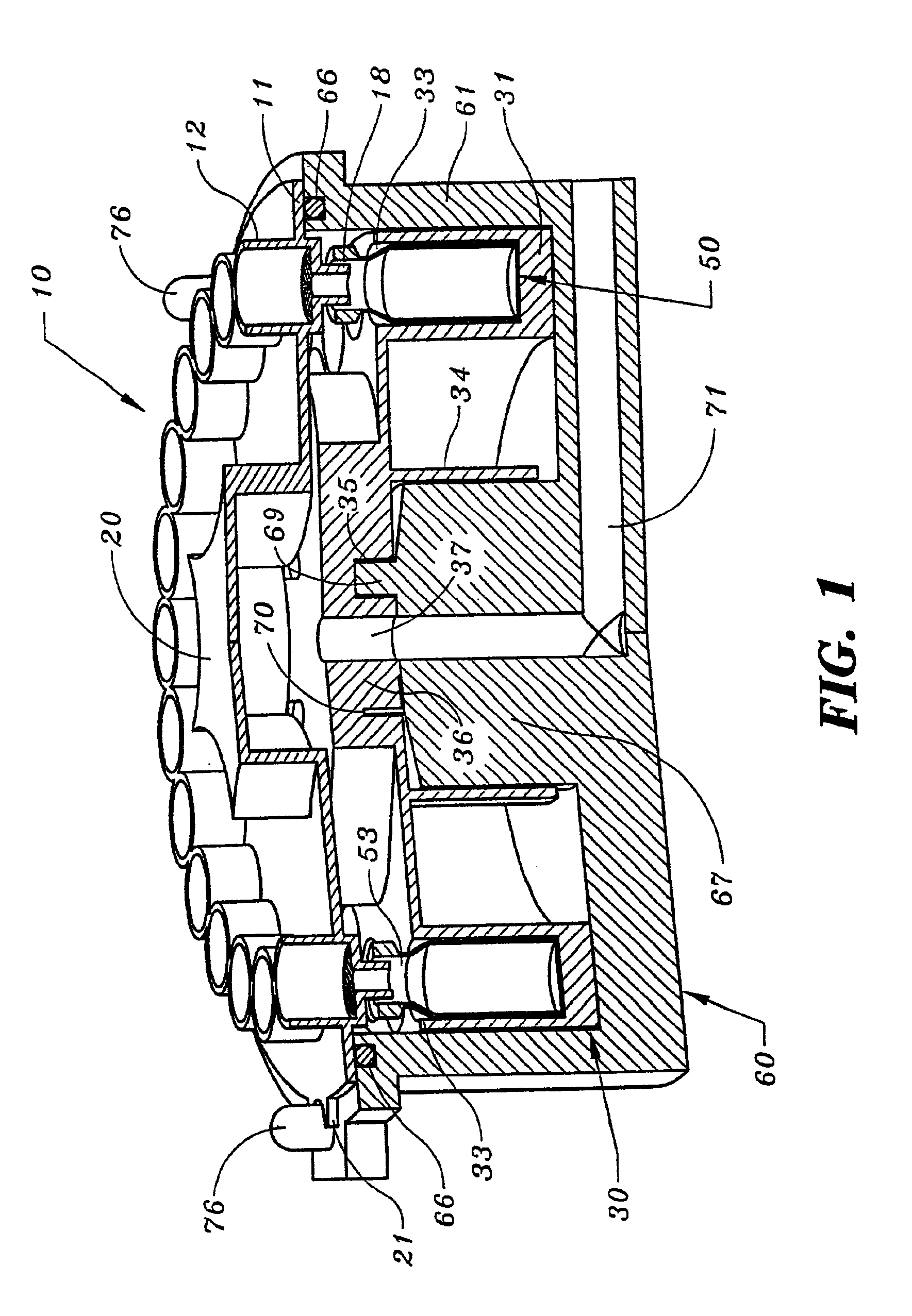
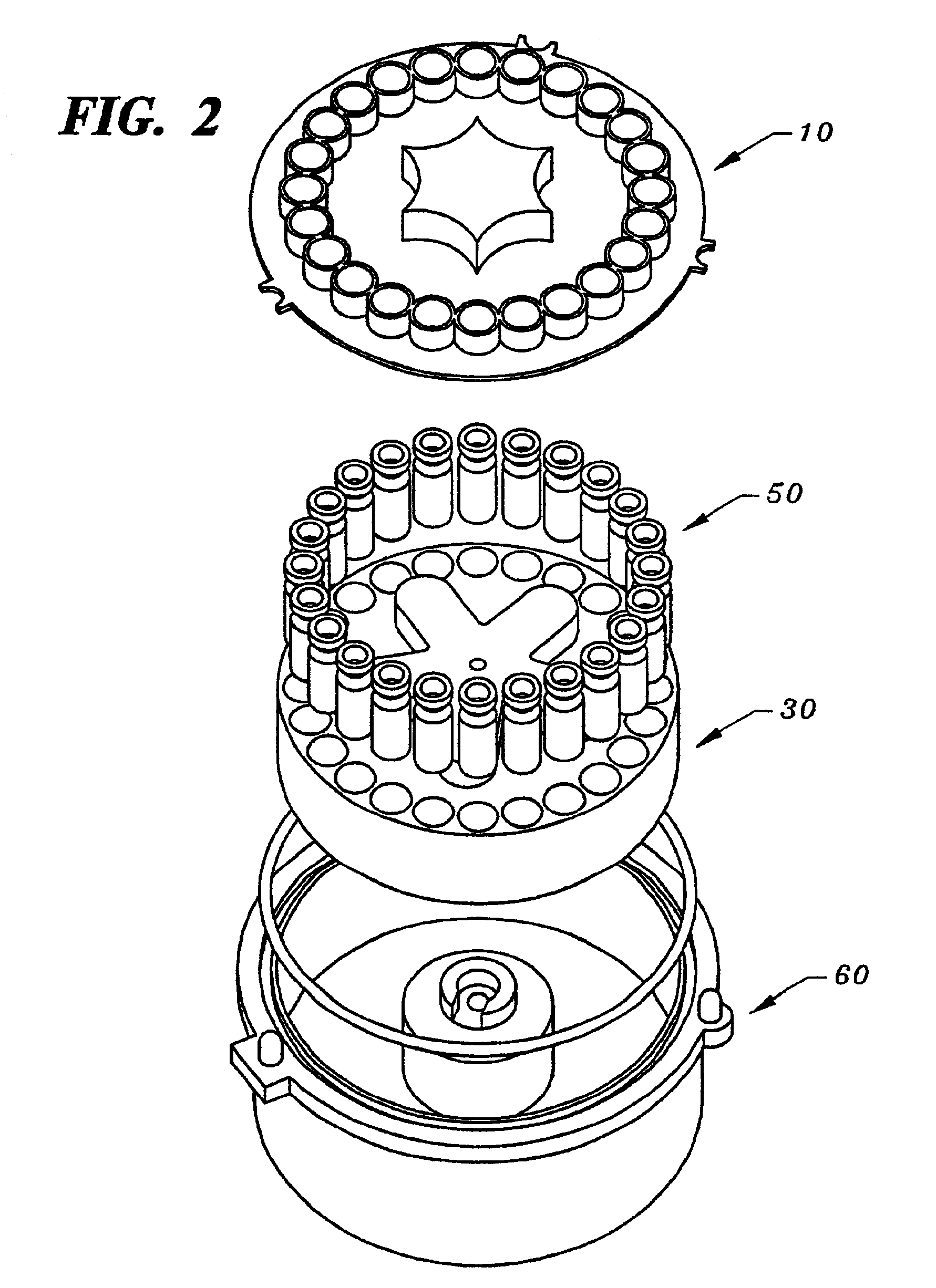
As shown in FIGS. 1 and 2, an exemplary test sample preparation device comprises a housing 60, a filter assembly 10, a sampler tray 30, a plurality of vials 50 and a key mechanism 21. The filter assembly 10 may include a plurality of wells 12, each of which contains a microporous filter 13 (FIG. 3a) or any suitable porous medium, such as a solid phase extraction medium. The vials 50 may be removably coupled to the sampler tray 30, and the sampler tray 30 and the vials 50 may be removably disposed in the housing 60. The filter assembly 10 may be removably connected to the housing 60, and the vials 50 preferably are in liquid receiving relationship with the wells 12, respectively. By applying a vacuum to the housing 60, test samples contained in the wells 12 may be passed through the filters 13 and deposited directly into the vials 50 in the sampler tray 30. The vials 50 and the sampler tray 30 may then be removed from the housing 60 and placed, for example, in an automated instrument...


PUM

PropertyMeasurementUnit
pressureaaaaaaaaaa
timeaaaaaaaaaa
vacuumaaaaaaaaaa

Abstract

The description describes a test sample preparation device comprising a housing, a filter assembly disposed over an opening in the housing and including a plurality of wells, a sampler tray removably disposed in the housing, and a plurality of vials removably coupled to the sampler tray and being in liquid receiving relationship with the wells. A filter assembly is also disclosed and which comprises a cover defining an impervious wall and plurality of wells formed in the wall, each wall having first and second open ends, the second open end of the well comprising a tubular protrusion. A housing is also disclosed and comprises a generally cylindrical body, a vacuum channel providing fluid communication between the interior and the exterior of the cylindrical body, and a key mechanism including a post having first and second ends, the key mechanism being arranged to orient a sampler tray and vials with respect to the housing. A method for simultaneously preparing multiple test samples for automated liquid chromatography and a method for automated liquid chromatography are also disclosed and comprise depositing test samples into a plurality of wells, simultaneously passing the test samples through porous media disposed in the wells, and depositing the filter test samples directly into vials removably coupled to a sampler tray.

Description

TECHNICAL FIELDThe present invention relates to devices and housings for preparing test samples.BACKGROUND OF THE INVENTIONCurrently, there are a number of conventional methods for preparing multiple test samples, such as test samples for automated liquid chromatography. One of the conventional methods involves filtering and depositing a test sample into each of a number of vials using a syringe and a syringe filter contained therein. The test samples generally are sequentially filtered and deposited into the vials. The vials may be placed in a sampler tray either before or after the test samples have been deposited in the vials. Then the sampler tray and vials are placed in an automated test instrument for liquid chromatography.Another conventional method of preparing multiple test samples involves the use of a test sample preparation device. Under this approach, the test samples are deposited into a number of wells, each of which contains a filter. A differential pressure across t...

Claims


Application Information

Patent Timeline
Patent Type & Authority Patents(United States)
IPC IPC(8): B01L3/00G01N30/04G01N1/10G01N30/24G01N35/02
CPCB01L3/50255G01N30/24Y10T436/25Y10T436/25375Y10T436/2575
Inventor SKLAR, ERIC R.DELBEN, DEAN C.VITKUSKE, DANIEL S.
Owner PALL CORP
Learn More