Optical system for compensating for non-uniform illumination of an object

an optical system and object technology, applied in the field of hand-held or portable optical scanners, can solve problems such as difficulty in uniform illumination, sources typically used to illuminate navigation areas, and inconvenient operation

Inactive Publication Date: 2005-04-12
HEWLETT PACKARD DEV CO LP
View PDF23 Cites 28 Cited by
  • Summary
  • Abstract
  • Description
  • Claims
  • Application Information

AI Technical Summary

Benefits of technology

An optical system for forming an image of at least a portion of an illuminated area on an object may comprise a lens positioned a spaced distance from the illuminated area on the object and an aperture stop positioned so that it is substantially co-planar with the image side focal plane of the lens. An occludi

Problems solved by technology

While such navigation systems are known and are being used, they are not without their problems.
For example, one problem associated with optical navigation systems of the type described above stems from the difficulty in uniformly illuminating the inherent structural features on the object so that the same may be detected by the navigation sensors.
The light sources typically used to illuminate the navigation areas (e.g., infra-red light emitting diodes (LEDs)) typically do not provide a uniform illumination pattern.
If the difference between the brightly illuminated regions and the less brightly illuminated regions is substantial, there is a significant chance that the navigation system will interpret the non-uniformity of illumination as fixed pattern noise, which may result in the navigation system producing a false navigation signal.
Such false navigation signals may

Method used


Image

  • Optical system for compensating for non-uniform illumination of an object
  • Optical system for compensating for non-uniform illumination of an object
  • Optical system for compensating for non-uniform illumination of an object

Examples


Embodiment Construction

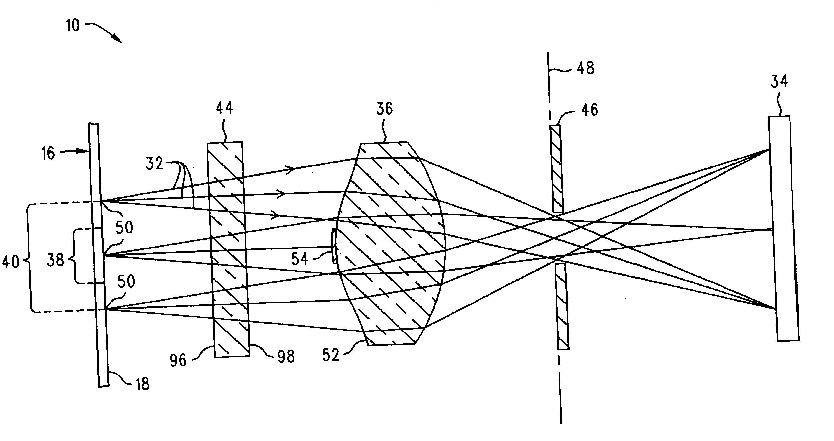
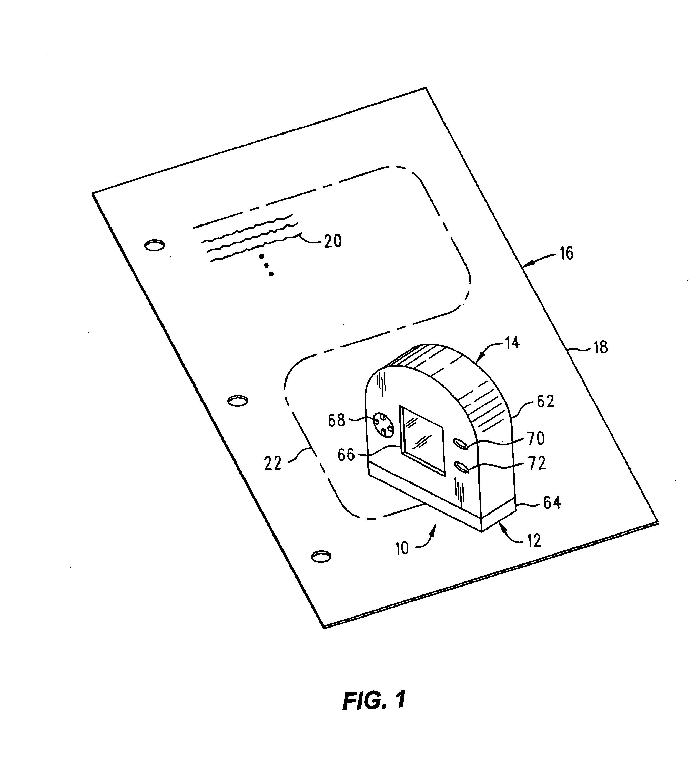
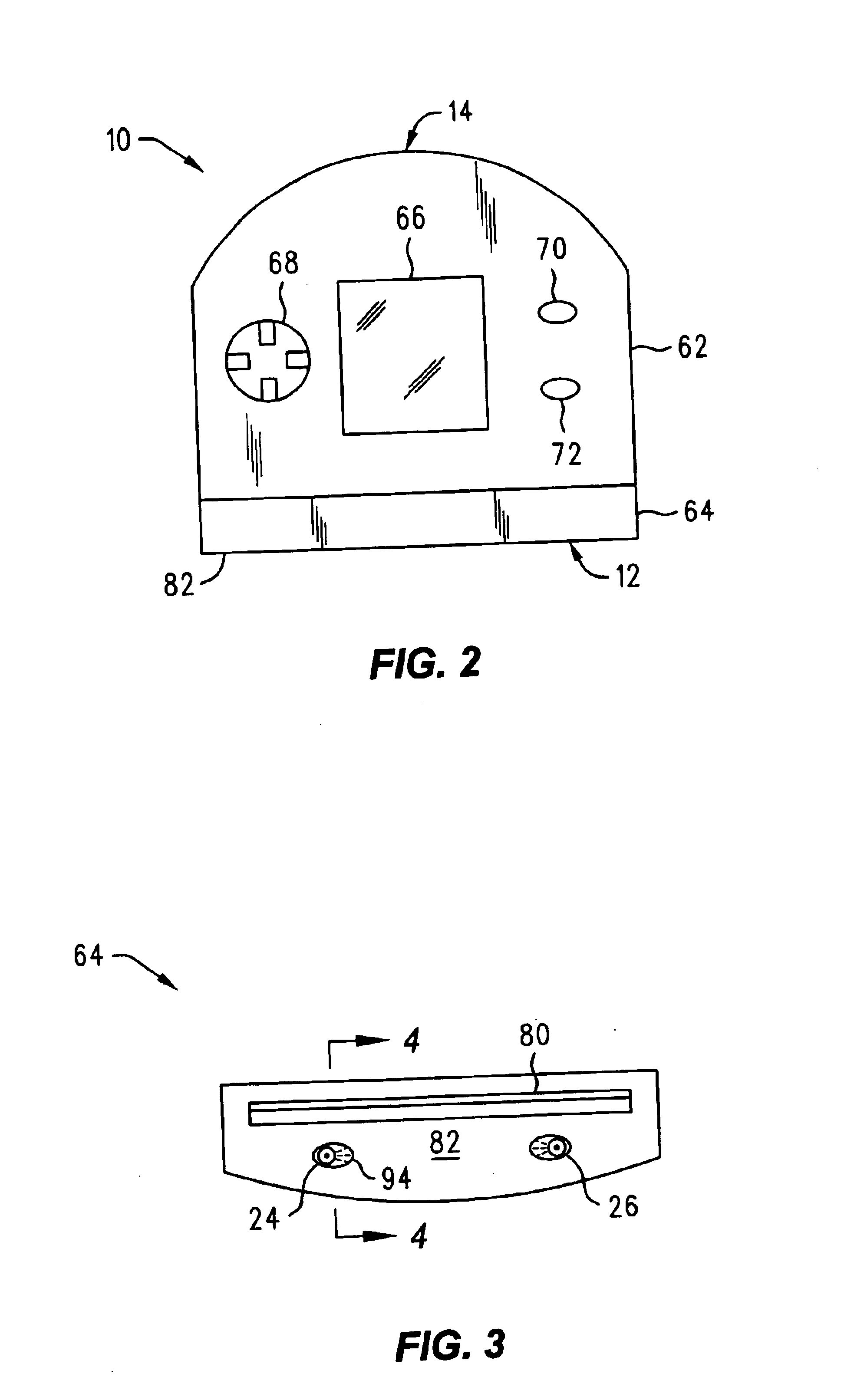
An optical system 10 (FIG. 7) for compensating for non-uniform illumination of an object is shown and described herein as it could be used in an optical navigation system 12 of the type that may be used in a portable or hand-held image scanner 14 (FIG. 1). As will be described in greater detail below, the optical system 10 compensates for the non-uniform illumination of the object from which navigation data are obtained, thereby enhancing the consistency and reliability of the navigation data produced by the optical navigation system 12.

In the exemplary application illustrated in FIG. 1, the portable or hand-held image scanner 14 may be used to scan an object 16, such as a document 18 with written text 20 provided thereon. The optical navigation system 12 provides position or navigation information to the scanner 14 thereby allowing the scanner 14 to scan documents of nearly any size regardless of the size of the portable image scanner 14. For example, the entire document 18 may be ...


PUM


Abstract

An optical system for forming an image of at least a portion of an illuminated area on an object may comprise a lens positioned a spaced distance from the illuminated area on the object and an aperture stop positioned so that it is substantially co-planar with the image side focal plane of the lens. An occluding element is positioned between the lens and the illuminated area on the object so that the occluding element blocks a predetermined amount of light from a brightly illuminated region in the illuminated area but does not substantially block light from a less brightly illuminated region in the illuminated area.

Description

FIELD OF INVENTIONThis invention relates to imaging devices in general and more specifically to hand-held or portable optical scanners having optical position sensing systems.BACKGROUNDOptical scanner devices are well-known in the art and may be used to produce machine-readable image data signals that are representative of a scanned object, such as a photograph or a page of printed text. In a typical scanner application, the image data signals produced by an optical scanner may be used by a personal computer to reproduce an image of the scanned object on a suitable display device, such as a CRT or a printer.A hand-held or portable optical scanner is an optical scanner which is designed to be moved by hand across the object or document being scanned. The hand-held scanner may be connected directly to a separate computer by a data cable. If so, the data signals produced by the hand-held scanner may be transferred to the separate computer “on the fly,” i.e., as the image data are colle...

Claims


Application Information

Patent Timeline
IPC IPC(8): G01B11/00H04N1/047H04N1/107G06T1/00
CPCG01B11/00H04N1/047H04N1/107H04N2201/04712H04N2201/04734H04N2201/04737H04N2201/04743
Inventor BOHN, DAVID D.
Owner HEWLETT PACKARD DEV CO LP
Why Eureka
Try Eureka