Neutral density color filters

a color filter and neutral density technology, applied in the field of neutral density color filter, can solve the problems of affecting the color properties of the display system, unable to accurately determine the effective light transmission of the system, etc., and achieve the effects of reducing the amount of light recycling, and increasing the transmission stability of the display system

Active Publication Date: 2005-04-12
TEXAS INSTR INC
View PDF7 Cites 42 Cited by
  • Summary
  • Abstract
  • Description
  • Claims
  • Application Information

AI Technical Summary

Benefits of technology

The present application describes embodiments of a neutral density color wheel filter. According to one embodiment, a non-reflective neutral density color wheel can be configured to substantially eliminate recycling of light between the color wheel and a light source. In some embodiments, the neutral density color wheel includes an opaque coating over one or more color segments (e.g., full color segments or neutral density color segments) with randomly placed transmissive regions. The transmissive regions can be configured to substantially transmit incident light and the opaque coating can be configured to substantially block or absorb the incident light. Alternatively, the transmissive regions can be configured to substantially block or absorb the incident light and the opaque coating can be configured to substantially transmit the incident light. The size and spacing of the transmissive regions within a particular color segment can be used to determine the effective light transmission of that particular color segment. The ratio of the area of the transmissive regions versus the area of the opaque surface can be adjusted according to a transmission rate required by a given application. The color segment with opaque coating and transmissive regions substantially eliminates light recycling due to the reflection from the color wheel. The light transmission from the color wheel is independent of the optics of a display system. This results in an increased transmission stability of the display system.

Problems solved by technology

This recycling of light between the color wheel and the light source increases the effective light transmission through the color wheel filter and detrimentally affects the color properties of a display system.
The light transmission through the color wheel becomes dependent upon the system optics and the effective light transmission of the system cannot be accurately determined.

Method used


Image

  • Neutral density color filters
  • Neutral density color filters
  • Neutral density color filters

Examples


Embodiment Construction

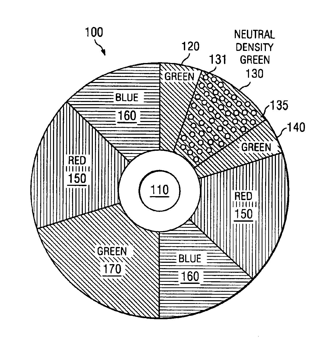
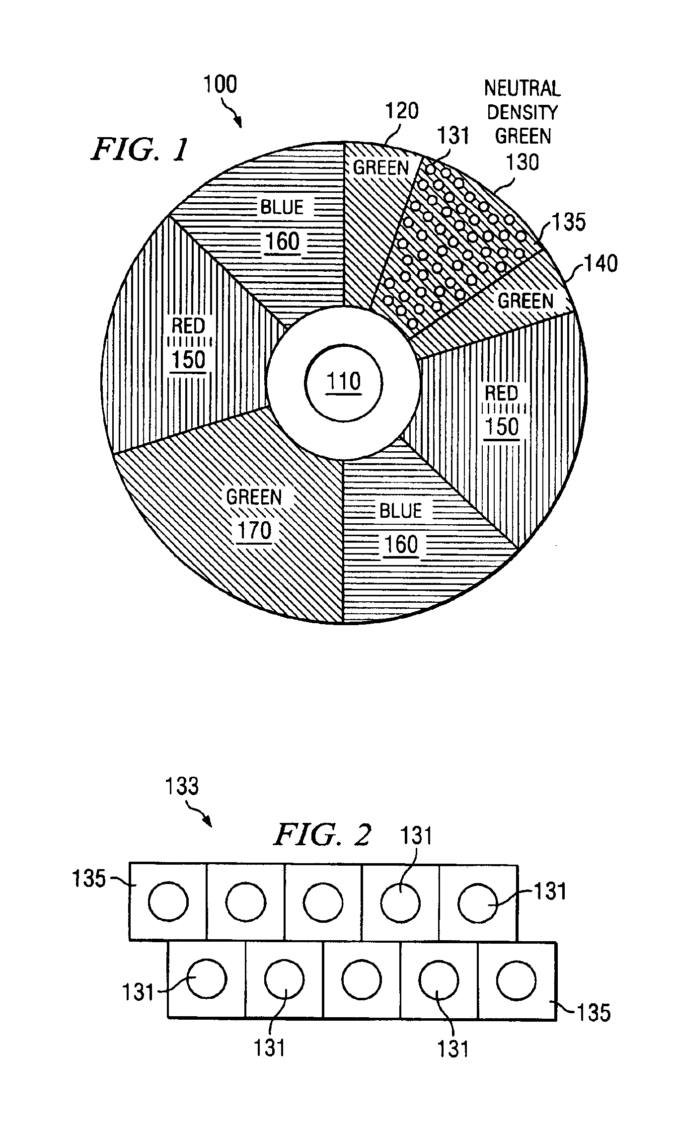
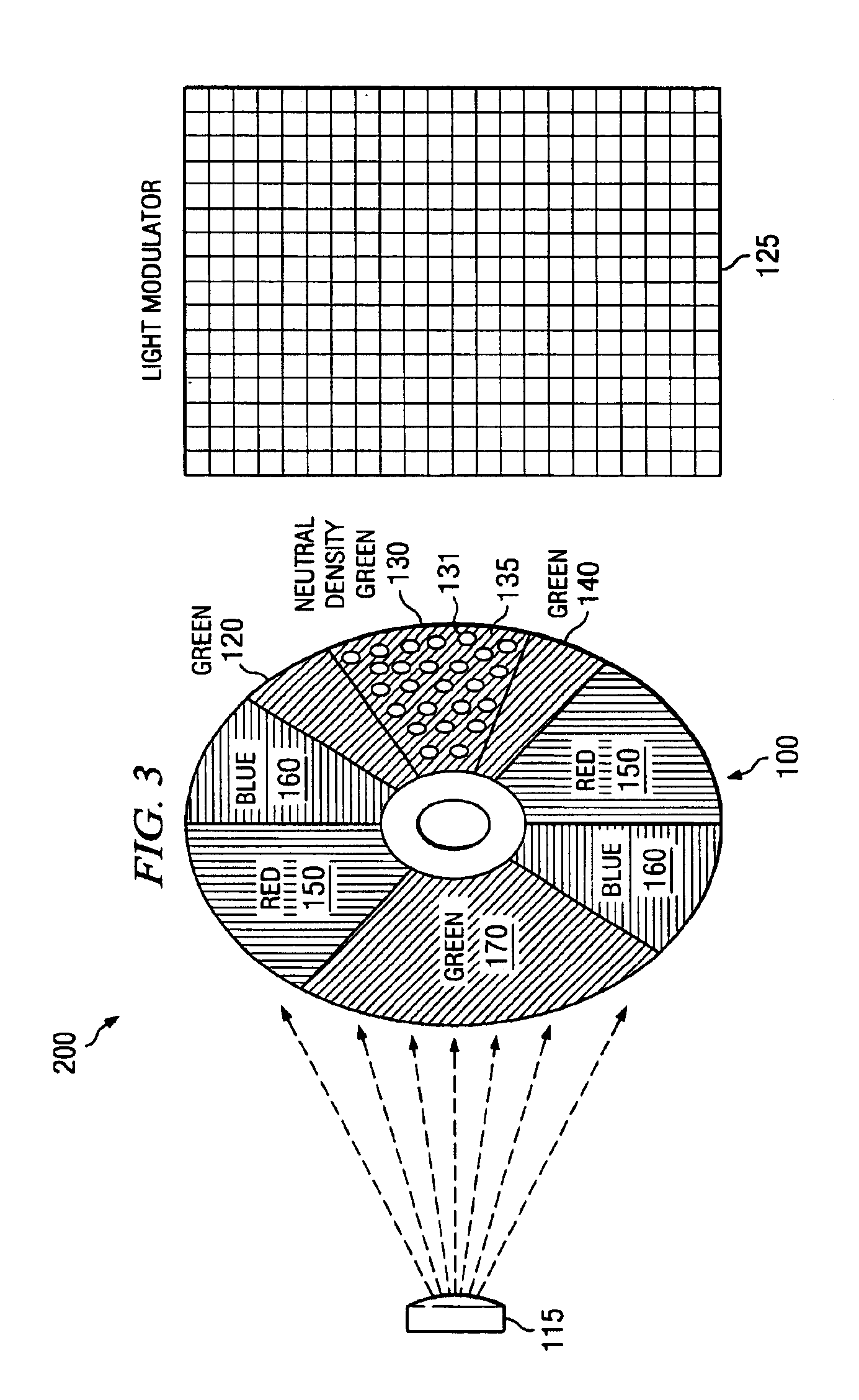
FIG. 1 illustrates an exemplary neutral density color wheel 100. The color wheel 100 includes a mounting 110 for a motor (not shown). The color wheel 100 further includes three green segments 120, 140, and 170, two red segments 150, and two blue segments 160. The color wheel 100 further includes a neutral density (“ND”) green segment 130, which is sandwiched between two green segments 120 and 140. For purposes of illustrations, one neutral density color segment is shown; however, one or more neutral density color segments can be included in any color segment. For example, one or more neutral density color segments can be included in each of the red, blue, and green color segments. Alternatively, one or more neutral density color segments can be placed between each color segment. Further, neutral density color segments can be placed anywhere within or adjacent to any color segment on the color wheel 100. The number, size, and placement of color segments on the color wheel 100 can be ...


PUM


Abstract

The present application describes embodiments of a neutral density color wheel filter. According to one embodiment, a neutral density color wheel (100) includes an opaque coating (135) over one or more color segments (120, 130, 140, 150, 160, 170) with randomly placed transmissive regions (131). The transmissive regions (131) can be configured to substantially transmit incident light and the opaque coating (135) can be configured to substantially block or absorb the incident light. Alternatively, the transmissive regions (131) can be configured to substantially transmit the incident light. The color segments with opaque coating (135) and transmissive regions (131) substantially eliminate light recycling due to the reflection from the color wheel. The light transmission from the color wheel (100) is independent of the optics of a display system.

Description

TECHNICAL FIELDThe present application describes neutral density color wheel filters for video display systems, and specific embodiments of a neutral density color wheel filter.BACKGROUNDGenerally, neutral density color wheel filters are used to provide more bits for data processing within a color segment time of the color wheel. Typically, a lower density color segment is included in the color wheel to extend the time required to process the least significant bit of a corresponding data sample. One such color wheel design is described by Hewlett et al. U.S. Pat. No. 5,812,303, disclosure of which is incorporated herein by reference in its entirety for all purposes. Typically, the neutral density color wheels are designed using a dielectric coating (e.g., Magnesium, Fluoride, and Aluminum) on the color wheel. The transmissivity of the dielectric coating is adjusted according to a given application.When light from a light source is incident upon conventional color wheel along an opti...

Claims


Application Information

Patent Timeline
Patent Type & Authority Patents(United States)
IPC IPC(8): G02B7/00
CPCG02B26/023G02B26/008
Inventor HEWLETT, GREGORY J.PENN, STEVEN M.PETTITT, GREG S.SEGLER, JR., DANA F.
Owner TEXAS INSTR INC
Why Eureka
Try Eureka