Channel sharing by diverse multiframes in a wireless communications network

a wireless communication network and multi-frame technology, applied in the field of wireless communications, can solve the problems of not supporting circuit-switched gsm service and negatively affecting overall network performance, and achieve the effects of facilitating the achieving of gsm-compatible packets, and reducing the cost of gsm services

Inactive Publication Date: 2005-04-12
LUCENT TECH INC +1
View PDF17 Cites 40 Cited by
  • Summary
  • Abstract
  • Description
  • Claims
  • Application Information

AI Technical Summary

Benefits of technology

According to a specific implementation of the diverse multiframe principles of the present invention, a first multiframe type is defined as having 51 frames for scheduling broadcast control channels in an environment in which cells/sectors are “time-grouped” to provide greater frequency reuse (i.e., in a EDGE-COMPACT-type environment). On the same frequency carrier as the 51 multiframe for broadcast control channels, a second multiframe type is defined as having 52 frames for scheduling

Problems solved by technology

Since EDGE-COMPACT does not have the 51 multiframe structure of GSM, it does not support circuit-switched GSM service.
Furthermore, because only a single 52 multiframe is used to schedule all transmissions in EDGE-COMPACT, it may be diffi

Method used


Image

  • Channel sharing by diverse multiframes in a wireless communications network
  • Channel sharing by diverse multiframes in a wireless communications network
  • Channel sharing by diverse multiframes in a wireless communications network

Examples


Embodiment Construction

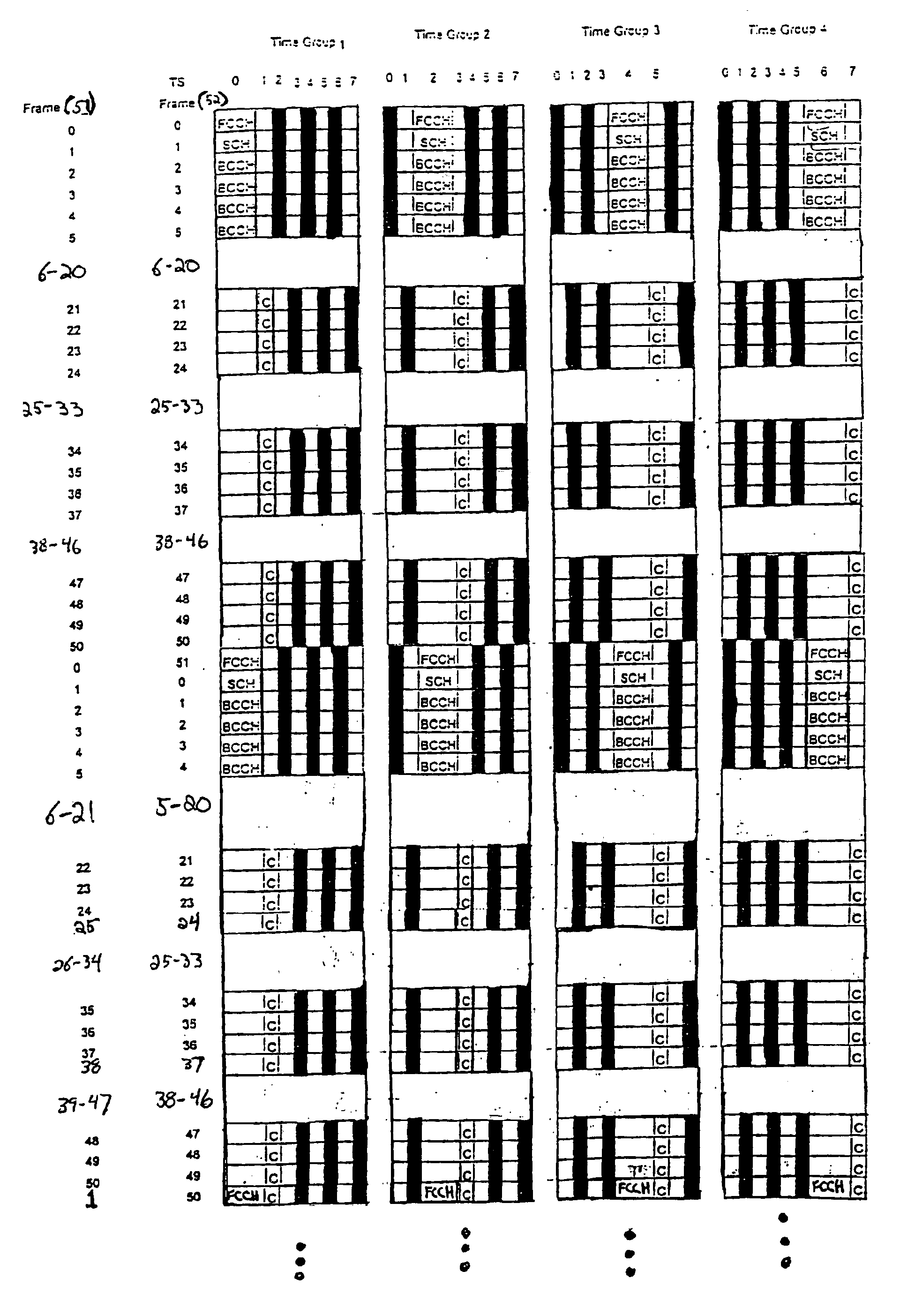
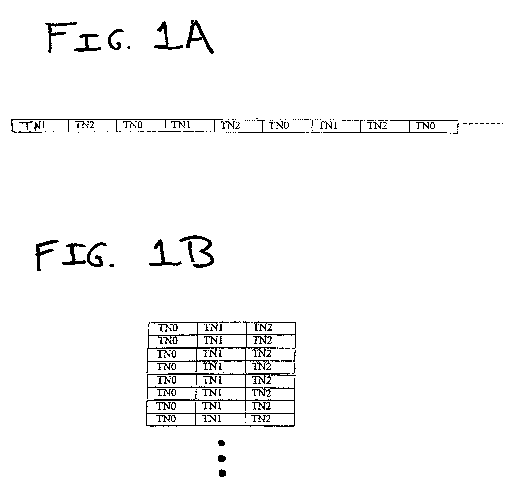
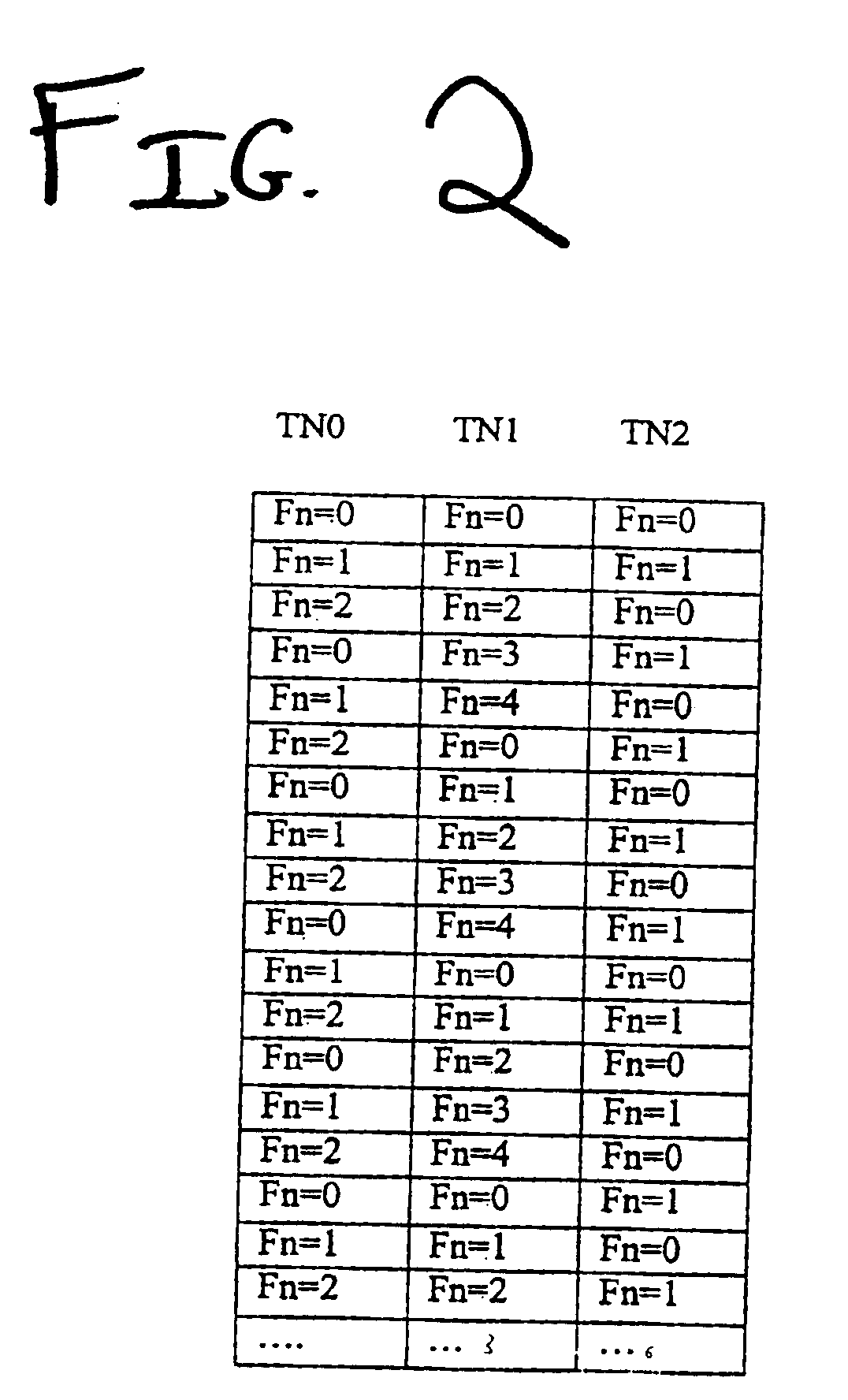
The present invention is a system and method for providing air interface channels in a wireless communications network. In accordance with the present invention, physical channels for a single frequency carrier are defined as time slots, a series of consecutive time slots define a frame, and a plurality of multiframe types are defined for the single frequency carrier as including different numbers of consecutive frames. By multiplexing a plurality of multiframe types onto a single frequency carrier, diverse channels types, such as traffic channels, broadcast control channels, and common control channels, are accommodated on the same frequency carrier to enable efficient utilization of frequency resources. The general principles of the present invention will be described below with reference to FIGS. 1A, 1B, and 2, and an exemplary implementation of the present invention will be described with reference to FIG. 3.

FIG. 1A illustrates a one-dimensional representation of an exemplary di...


PUM


Abstract

A wireless communication system and method provide air interface channels using diverse multiframe types on a single frequency carrier. Physical channels for a single frequency carrier are defined as time slots, a series of consecutive time slots define a frame, and a plurality of multiframe types are defined for the single frequency carrier as including different numbers of consecutive frames. By multiplexing a plurality of multiframe types onto a single frequency carrier, diverse channels types such as traffic channels, broadcast control channels, and common control channels can be accommodated on the same frequency carrier to enable efficient utilization of frequency resources. In one exemplary implementation, a first multiframe type is defined as having x consecutive frames, a second multiframe type is defined as having y consecutive frames, and a third multiframe type is defined as having z consecutive frames. Thus, the frame number for the first multiframe type is counted modulus x, the frame number for the second multiframe type is counted modulus y, and the frame number for the third multiframe type is counted modulus z. The first, second, and third multiframe types are further assigned to different time slots. For example, if a frame is defined as having three time slots, the first multiframe type may be assigned to the first time slot, the second multiframe type may be assigned to the second time slot, and the third multiframe type may be assigned to the third time slot.

Description

BACKGROUND OF THE INVENTION1. Field of the InventionThe present invention relates to the field of wireless communications.2. Description of Related ArtIn wireless communications networks that use time division multiple access (TDMA), radio interface channels are defined as time slots on a given frequency. A particular channel uses the same repeating time slot, resulting in mutual orthogonality between different channels in time. The duration between when a given time slot repeats is called a frame, and multiple frames are typically organized into a larger logical structure called a multiframe. Multiframe size may vary depending on the type of information (i.e. “logical channel”) the multiframe is designed to carry. As a rule, however, all time slots on a given frequency have the same type of frame and the same type of multiframe, such that only different frequencies may have different multiframe structures.A wireless communications network that operates in accordance with the Global...

Claims


Application Information

Patent Timeline
IPC IPC(8): H04B7/26H04J3/00H04W16/02H04W72/04
CPCH04B7/2643
Inventor HUO, DAVID D.
Owner LUCENT TECH INC
Why Eureka
Try Eureka