Distance-measuring device

a technology of distance measurement and measuring device, which is applied in the field of distance measurement system, can solve problems such as inability to detect, and achieve the effects of avoiding irregularities, increasing resolution, and full maneuvering capability of the vehicl

Active Publication Date: 2005-04-12
ROBERT BOSCH GMBH
View PDF2 Cites 12 Cited by
  • Summary
  • Abstract
  • Description
  • Claims
  • Application Information

AI Technical Summary

Benefits of technology

The distance-measuring device of the present invention has the 
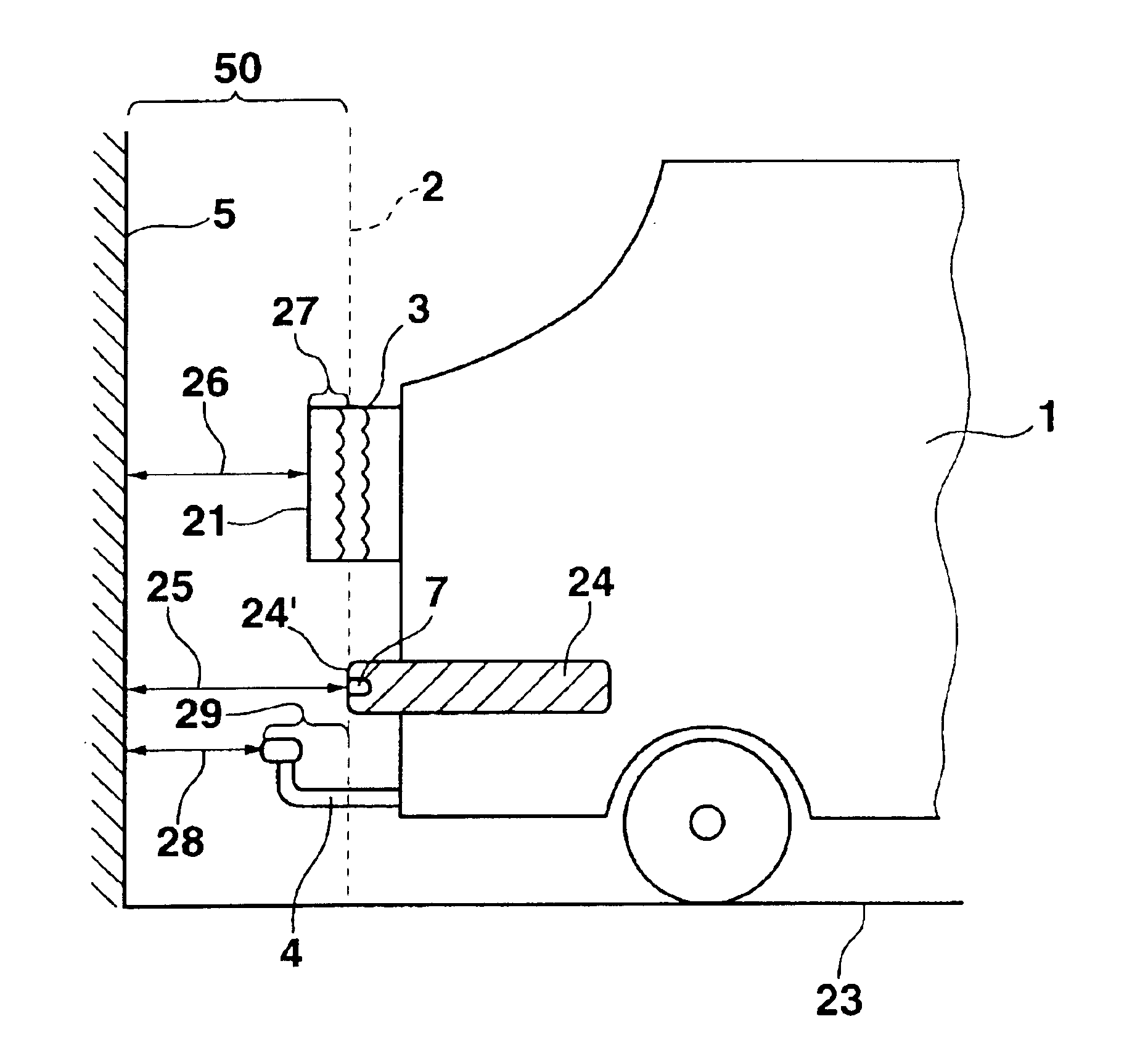
advantage that the dimensions of parts which are mounted on the vehicle and which extend into a spatial area between a detecting device and the obstacle are taken into account when determining the distance between the vehicle and the obstacle. The driver is thereby relieved when parking of independently having to separately calculate in the extension of those parts mounted on the vehicle which jut out beyond the remaining vehicle contour. On one hand, these may be vehicle parts themselves, add-ons to the vehicle, but also parts merely being transported by the vehicle. They are, in particular, such parts able to be mounted on the vehicle which do not belong to the vehicle body as such, and which are either arranged as removable mass-produced components on the vehicle that are later mounted as additional equipment on the vehicle, or which are optionally secured in a removable fashion on or in the vehicle for a temporary time. To be understood here are components which are not necessary for the driving function of the vehicle and which in general offer an additional use to the user that is not necessary for all users of the vehicle, at least not for the entire usage duration. Examples for this are, for instance, a spare wheel additionally positioned on the back of the vehicle, a bicycle likewise situated on the back of the vehicle, particularly in the case of buses or minibuses, a trailer hitch, a load jutting out beyond the vehicle contour such as a special luggage rack or a piece of luggage protruding out of the trunk or a tailgate, or a projecting plate such as a license plate or a warning plate. When using the distance-warning device of the present invention, the driver can be certain that the minimum distance to be observed by him / her between the parts additionally mounted on the vehicle, and therefore between the vehicle, and an obstacle is maintained during a driving maneuver. To this end, it is equally possible for the 
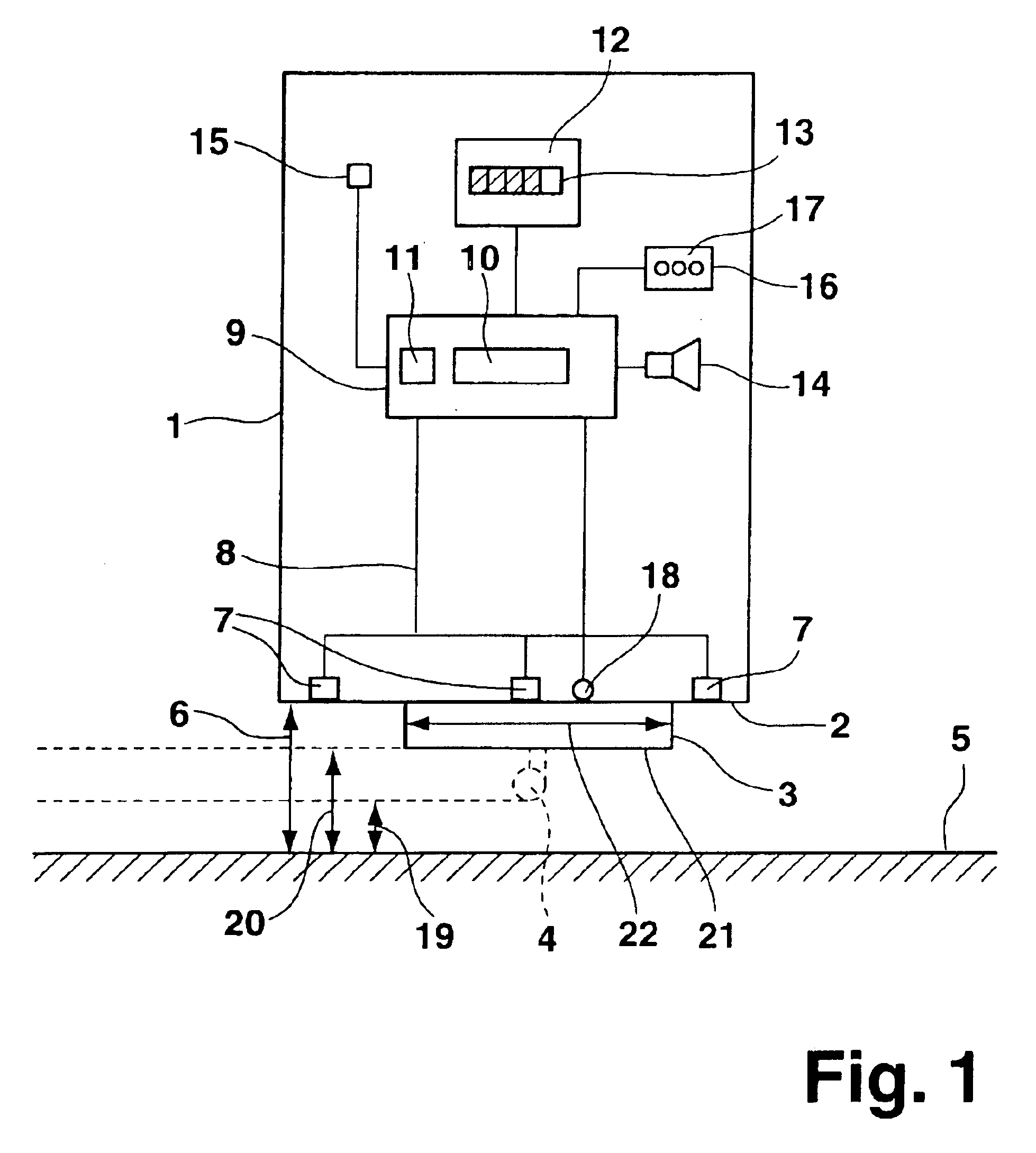
minimum distance to be observed to be increased by an evaluation unit, or, with the same effect, for the measured distance between the detecting device and the obstacle to be reduced correspondingly by calculation so that a warning of an equal nature may be output to a driver.
It is particularly advantageous for a sensor to automatically detect the mounting of the part projecting beyond the vehicle contour and into the space between the detecting device and the obstacle. In this manner, the distance-measuring device is able to determine the distance so that, on one hand, the full maneuvering capability of the vehicle may be utilized when the part is not mounted, while on the other hand, a possible collision can be avoided.
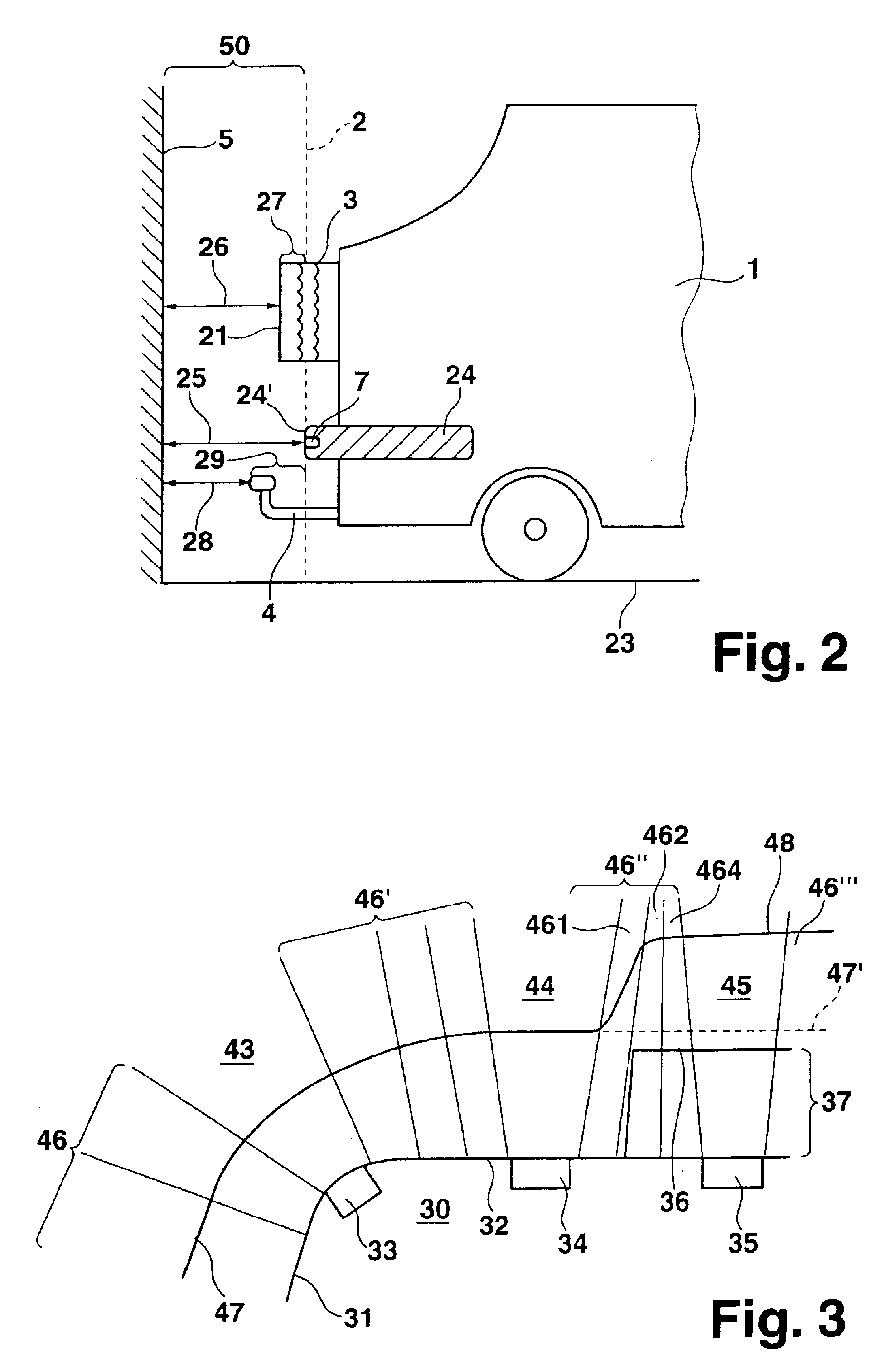
It is particularly advantageous to equip the detecting device with a plurality of individual sensors whose data may be evaluated both individually and separately. On one hand, a larger spatial area may thereby be covered, and on the other hand, it is also advantageously possible to link the measurement data of different sensors to one another in order to increase the resolution and, in particular, to spatially locate an obstacle or determine the shape of the obstacle.
It is also advantageous to assign zones to the individual sensors, so that as a function of the part projecting into the space between the detecting device and the obstacle, each zone may be assigned a corresponding offset value that is subtracted from the distance measured between the detecting device and the obstacle or that is added to a minimum distance to be observed in the respective zone. The evaluation by calculation is thereby simplified to the effect that a specific distance value does not have to be determined for each spatial coordinate, but rather only for each zone. In particular, a smooth transition between distance boundaries makes it possible to avoid irregularities in the detection curve and therefore fluctuating measuring results in the display for the distance warning provided for the driver.

Problems solved by technology

Thus, for example, obstacles located very close to the vehicle may lie in a dead angle of the sensor, so that they cannot be detected.
However, if the user makes structural changes on the vehicle, the minimum distance remains unchanged, so that the vehicle may collide with an obstacle without the driver being warned by the distance-measuring device.

Method used


Image

  • Distance-measuring device
  • Distance-measuring device
  • Distance-measuring device

Examples


Embodiment Construction

The present distance-measuring device is used in particular for motor vehicles, and in this context, is used primarily for driving maneuvers at low speeds, for example, when parking in a parking space. Components jutting out on any side of the vehicle beyond the remaining contour of the vehicle may be taken into account. In the following, the present invention is explained in terms of an exemplary embodiment in which components are mounted on the rear of the vehicle so that they jut out beyond the bumper.

FIG. 1 shows a motor vehicle 1, on whose vehicle rear 2 a spare wheel 3 is mounted that, in a top view as shown in FIG. 1, projects beyond a bumper forming and terminating vehicle rear 2. Optionally, a trailer hitch 4, shown with a dotted line in FIG. 1, may additionally project beyond vehicle rear 2. Motor vehicle 1 is aligned with its vehicle rear 2 parallel to a house wall 5. Vehicle rear 2 has a first distance 6 to house wall 5. Arranged on vehicle rear 2 are three sensors 7 pre...


PUM


Abstract

A distance-measuring device is used for measuring a distance between a vehicle and an obstacle. In so doing, dimensions of additional parts that are to be mounted on the vehicle and that project into a space between a detecting device for the distance measurement and the obstacle are taken into account.

Description

BACKGROUND INFORMATIONDistance-measuring systems in motor vehicles for supporting parking, in which sensors for measuring distance are arranged on the vehicle, are already known. The sensors are implemented in particular as ultrasonic sensors which send out an ultrasonic signal to an obstacle that is reflected again from the obstacle. The distance between the ultrasonic sensor and the obstacle is then determined from the propagation time. The sensors for measuring distance are preferably integrated in a bumper of the vehicle, so that the distance between the bumper and the obstacle is determined. In measuring, on the one hand, direct measurements may be carried out in which the transmitting sensor itself senses the reflective signal again. On the other hand, cross measurements are also possible in which a different sensor senses the reflected signal. If the obstacle is getting closer to the vehicle, corresponding distance information is output to the driver indicating the obstacle t...

Claims


Application Information

Patent Timeline
Patent Type & Authority Patents(United States)
IPC IPC(8): B60Q1/48B60Q1/26G01S15/00G01S15/87G01S15/93G01S7/526G01S7/523G01S15/931
CPCB60Q9/006B60Q9/007G01S15/931G01S15/87G01S7/526
Inventor HOENES, FRANKKRAUSE, ULRICH
Owner ROBERT BOSCH GMBH
Why Eureka
Try Eureka