Crimping device for crimping crimp pieces of a metal terminal

a technology of crimping device and metal terminal, which is applied in the direction of metal working apparatus, connection formation by deformation, manufacturing tools, etc., can solve the problems of reducing the reliability of electrical connections correspondingly, and achieving the effect of enhancing crimping performan

Inactive Publication Date: 2005-04-19
YAZAKI CORP
View PDF12 Cites 11 Cited by
  • Summary
  • Abstract
  • Description
  • Claims
  • Application Information

AI Technical Summary

Benefits of technology

[0010]The present invention has been devised with a view to overcoming the drawbacks of the related device, and an object of the present invention is to provide a crimping device for crimping crimp pieces of a metal terminal wherein when the crimp pieces of the metal terminal are formed by the crimping device, the interference of the tips of the front legs, which are free ends, is suppressed to a minimum to deepen the biting into the core strand, thereby enhancing the crimping performance, i.e., the electrical connection performance.

Problems solved by technology

For this reason, the force FY with which the tips of the front legs bite into the core strand 4 becomes weak correspondingly, and it becomes difficult to obtain predetermined clamp strength, thereby possibly causing a decline in the reliability of electrical connection correspondingly.
For this reason, since this component of force FX acts in the direction in which the two tips interfere with each other, the biting into the core strand 4 becomes shallow in the same way as FIGS. 6A to 6C, possibly leading to the impairment of the reliability.

Method used


Image

  • Crimping device for crimping crimp pieces of a metal terminal
  • Crimping device for crimping crimp pieces of a metal terminal
  • Crimping device for crimping crimp pieces of a metal terminal

Examples


Embodiment Construction

[0027]Preferred embodiments of the present invention now will be described with reference to FIGS. 1A to 5.

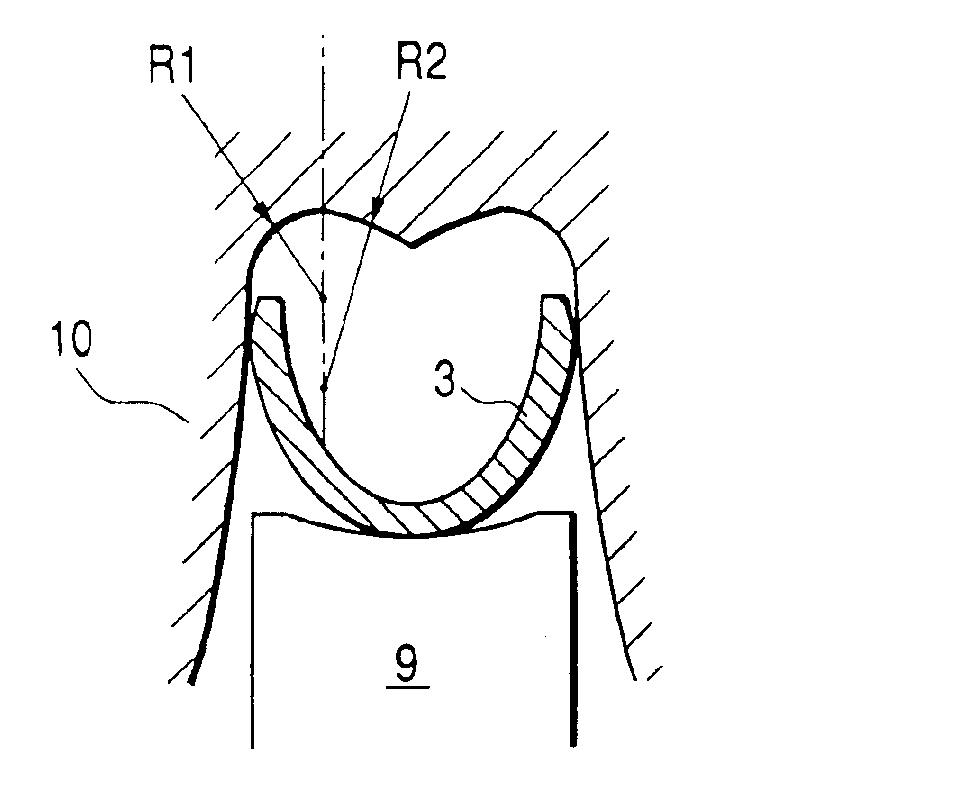
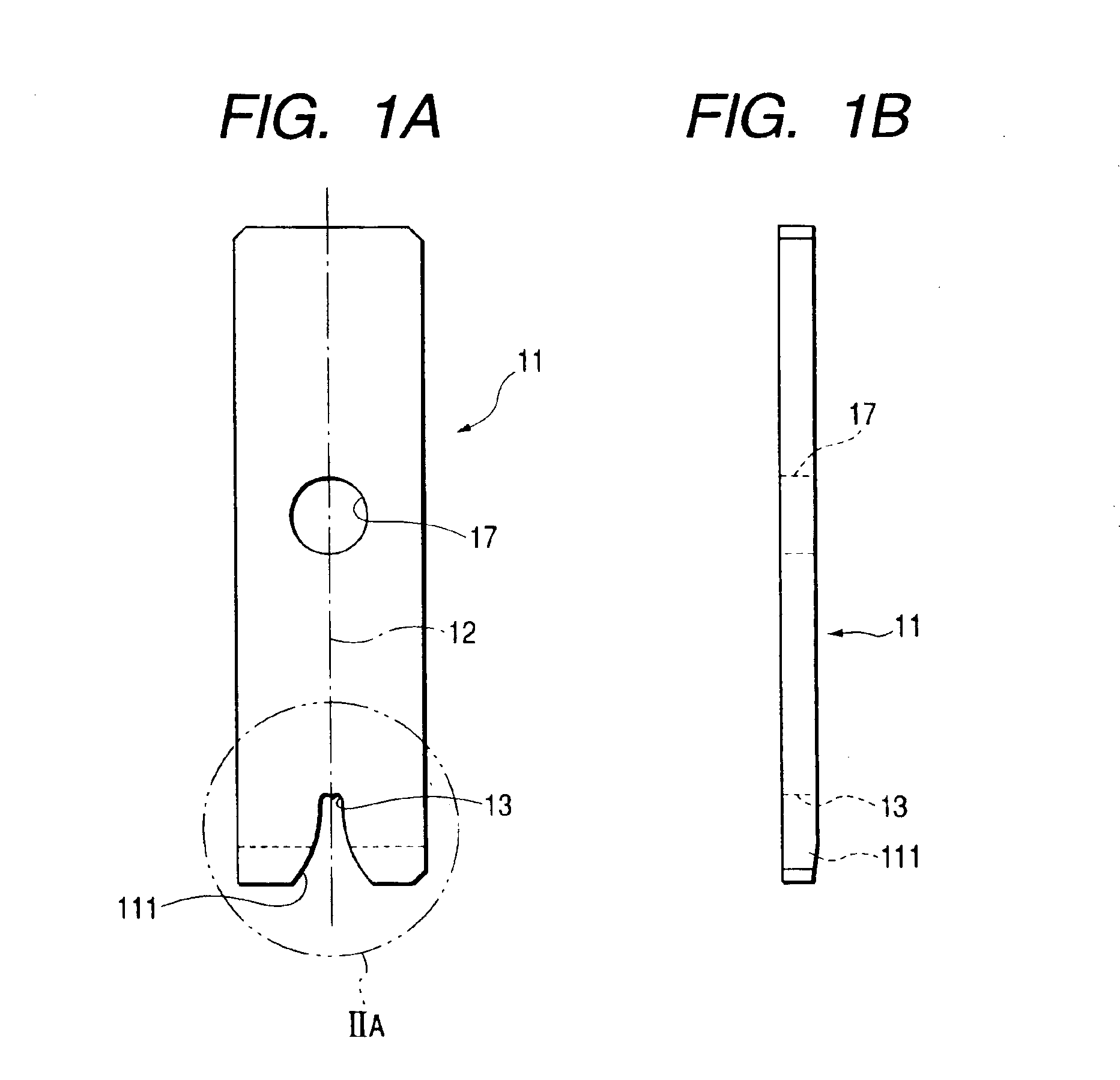
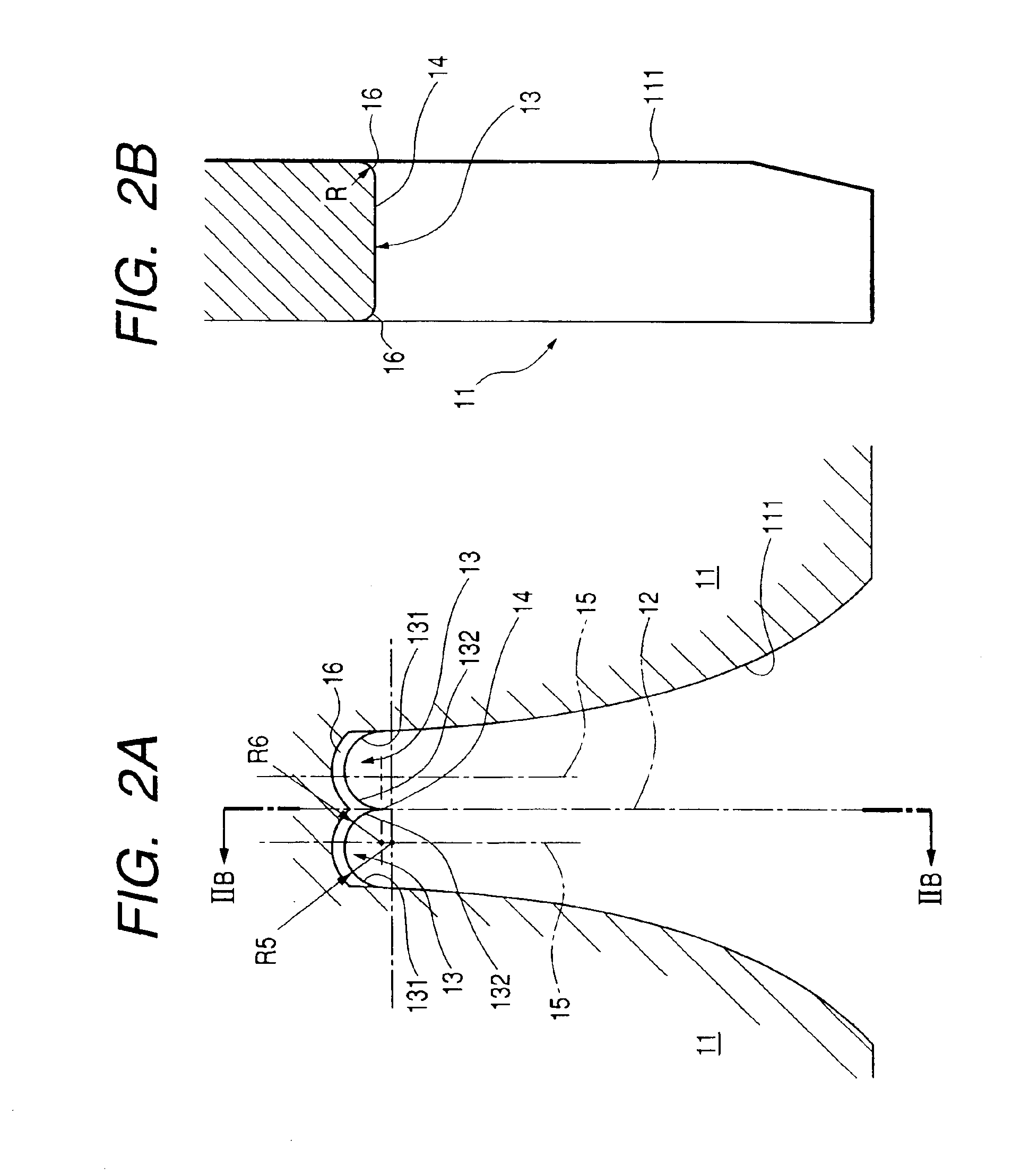
[0028]FIG. 1A is a front elevational view of a crimp indenter, i.e., a crimper 11, and FIG. 1B is a side elevational view thereof. The crimper 11 is a component element of a crimping device for crimping crimp pieces of a metal terminal, and two arch-shaped portions 13 are formed on an inner surface, corresponding to an apex, of a chevron-shaped groove 111 of the crimper 11 in such a manner as to be adjacent to each other and symmetric with respect to a plane including a longitudinal center axis 12 of the crimper. The curves which form the arch-shaped portions intersect on the longitudinal center axis, and a point of their intersection forms a sharply pointed portion 14. Reference numeral 15 denotes a parallel straight line which is parallel with the longitudinal center axis 12 and which passes vertically across the apex portion of the arch-shaped portion 13. In addition, this c...


PUM

PropertyMeasurementUnit
curvatureaaaaaaaaaa
radius of curvatureaaaaaaaaaa
angular shapeaaaaaaaaaa

Abstract

Crimp pieces (21) of a metal terminal and a conductor wire placed on an inner side of the crimp pieces are positioned between a crimp indenter (11) and a crimp anvil (18). Then, at least one of the crimp indenter (11) and the crimp anvil (18) is moved toward another one thereof along a direction of a longitudinal center axis (12) to crimp the crimp pieces (21). At least two arch-shaped portions (13) are disposed on an inner surface of the crimp indenter (11), and are adjacent to each other and symmetric with respect to a plane including the longitudinal center axis (12). A sharply pointed portion (14) is defined by curves of the at least two arch-shaped portions (13) intersecting on the longitudinal center axis (12). Curvature of each of the curves is set to be greater toward the sharply pointed portion (14).

Description

BACKGROUND OF THE INVENTION[0001]1. Field of the Invention[0002]The present invention relates to improvements of a crimping device for crimping crimp pieces of a metal terminal in which the improvement of electrical connection performance is made by increasing the mechanical clamp strength.[0003]The present application is based on Japanese Patent Application No. 2000-059037, which is incorporated herein by reference.[0004]2. Description of the Related Art[0005]In a case where a covered wire is connected to a metal terminal by crimping, the covered wire with a covering at its tip portion peeled off is placed in such a manner as to be sandwiched between a pair of front legs and a pair of rear legs, respectively, which are crimp pieces of the metal terminal, and are crimped by a clamping motion of a crimping device, thereby making it possible to obtain electrical connection performance with predetermined mechanical strength.[0006]For example, in a case where a female metal terminal 2 i...

Claims


Application Information

Patent Timeline
Patent Type & Authority Patents(United States)
IPC IPC(8): H01R43/048H01R43/04
CPCH01R43/048Y10T29/53226Y10T29/49179Y10T29/53235
Inventor KITAGAWA, HIRONORIITO, NAOKITAKAYAMA, TSUTOMU
Owner YAZAKI CORP
Why Eureka
Try Eureka