Refrigerating cycle apparatus
a cycle apparatus and refrigerating technology, which is applied in the direction of refrigeration components, indirect heat exchangers, lighting and heating apparatus, etc., can solve the problems of insufficient loss of energy used to suck refrigerant from the evaporator, difficult to facilitate the flow of refrigerant in the evaporator, and difficult to cope with such wide load changes. , to achieve the effect of restricting the cycle performance deterioration
- Summary
- Abstract
- Description
- Claims
- Application Information
AI Technical Summary
Benefits of technology
Problems solved by technology
Method used
Image

Examples
first embodiment
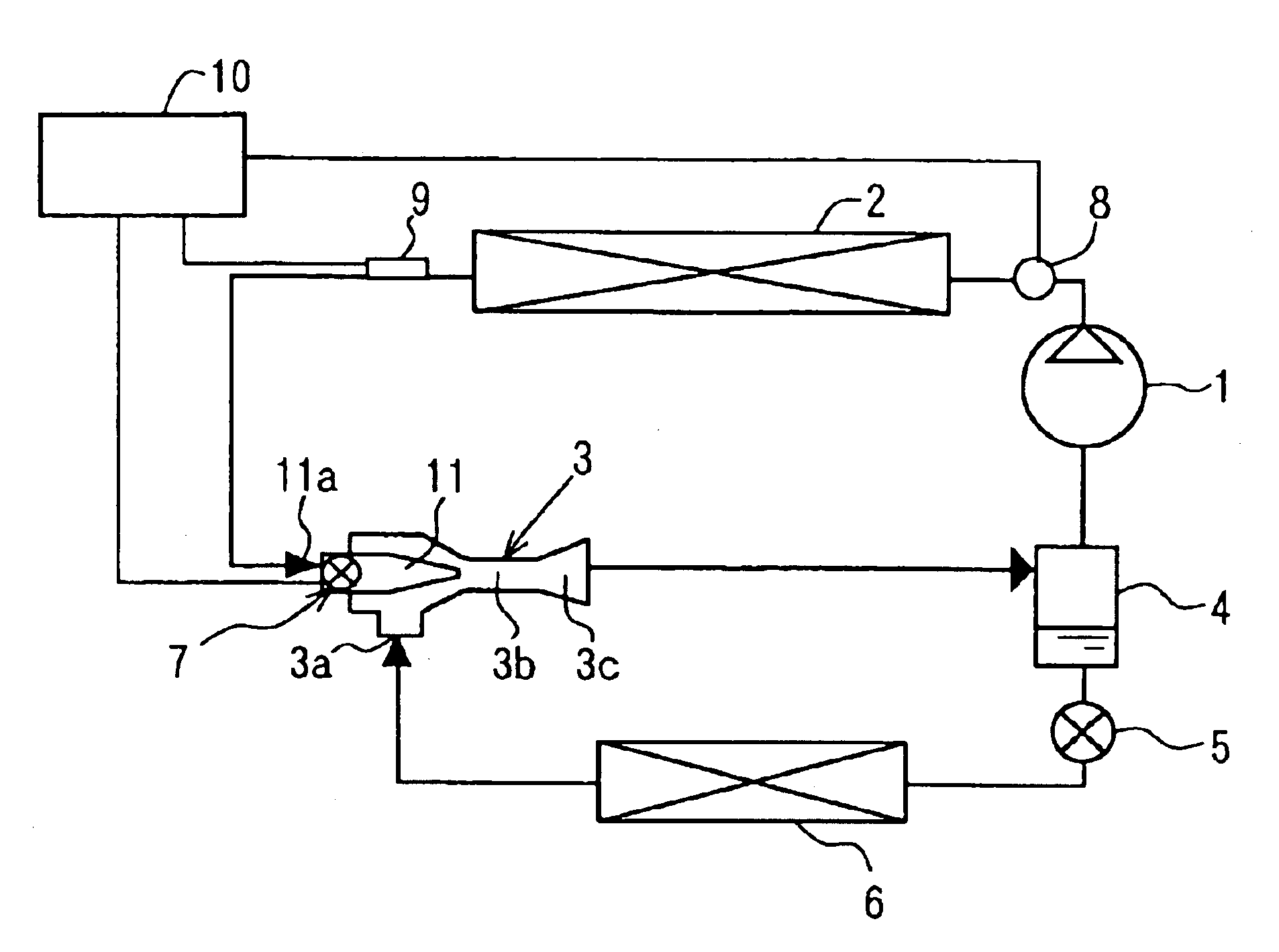
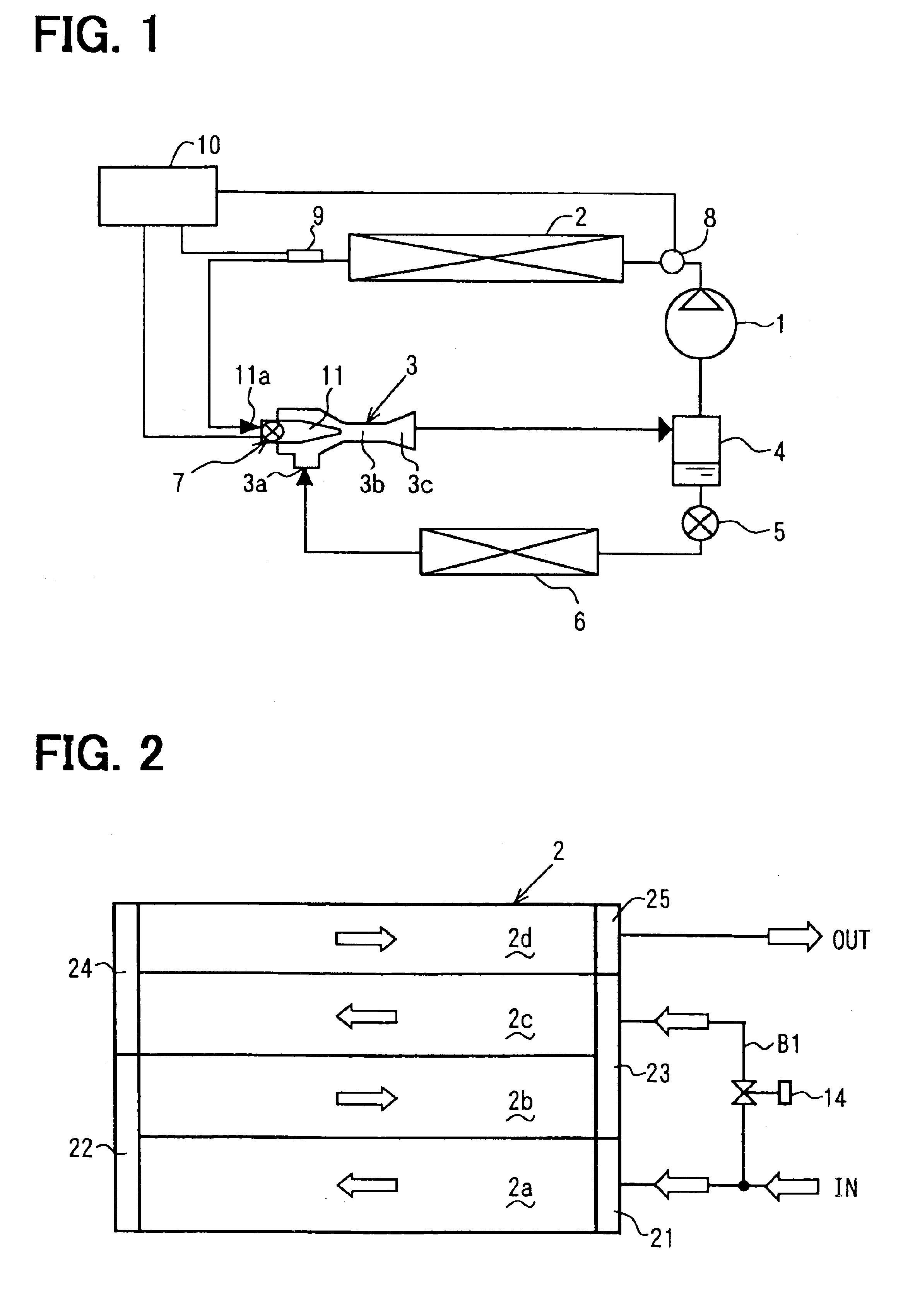
[0030]Referring to FIG. 1, a refrigerating cycle of the present invention is for example employed to an air conditioning apparatus for a vehicle. The refrigerating cycle is an ejector cycle in which a refrigerant compressor 1, a gas cooler (refrigerant radiator) 2, an ejector 3 and a gas-liquid separator 4 are connected in a loop through refrigerant pipes. The ejector cycle further includes a pressure-reducing device 5 and a refrigerant evaporator 6. A liquid refrigerant outlet of the gas-liquid separator 4 and a low-pressure inlet 3a of the ejector 3 are connected to each other through a bypass pipe. The pressure-reducing device 5 and the refrigerant evaporator 6 are provided on the bypass pipe.
[0031]In the cycle, carbon dioxide (CO2), which has a low critical temperature, is used as a refrigerant, for example. The ejector cycle constructs a super critical vapor compression-type ejector cycle in which the refrigerant is compressed in the compressor 1 so that pressure of the refrige...
second embodiment
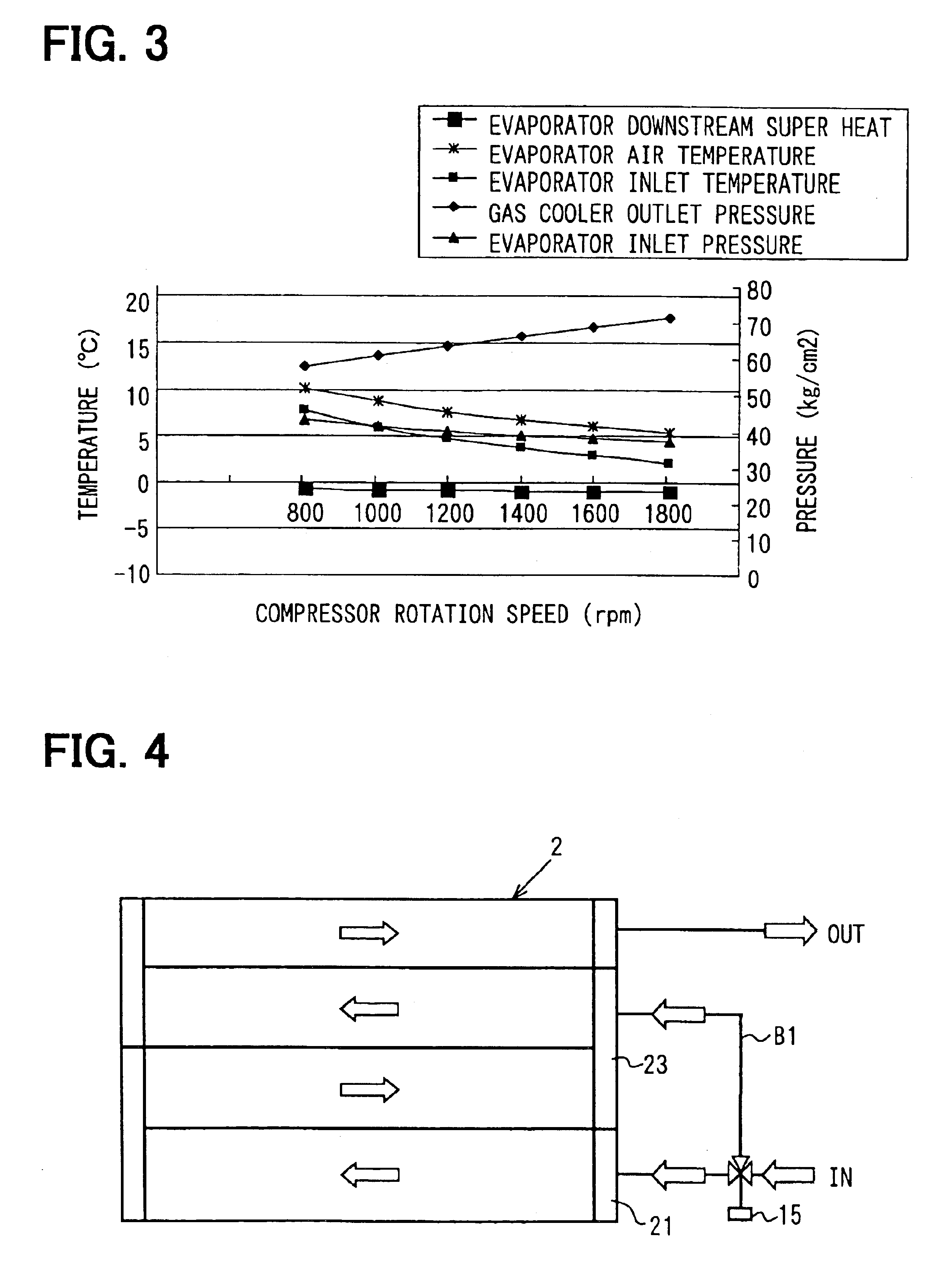
[0055]In the second embodiment, the heat radiation reduction member of the gas cooler 2 has a three-way valve or a flow rate distribution valve 15, in place of the switching valve 14 of the first embodiment, as shown in FIG. 4. The valve 15 switches the refrigerant flow between the normal path and the bypass passage B1. BY the valve 15, one of the normal path, the bypass passage B1, and both the bypass passage B1 and the normal path is selected for the refrigerant passage, depending on the load condition of the cycle. When the refrigerant is introduced into both the normal path and the bypass passage B1, the flow rates or distribution rates of the refrigerant to the normal path and the bypass passage B1 are adjusted by the valve 15.
third embodiment
[0056]In the third embodiment, as shown in FIG. 5, the heat radiation reduction member of the gas cooler 2 includes a bypass passage B2 and a flow rate control valve 16. The bypass passage B2 is provided to connect between the inlet pipe and the outlet pipe of the gas cooler 2. The flow rate control valve 16 is provided in the bypass passage B2 for switching the refrigerant passage between the normal path and the bypass passage B2. The flow of the refrigerant is switched between the normal path in which the refrigerant flows in the gas cooler 2 through the normal path and a two way mode in which the refrigerant flows through both the normal path and the bypass passage B2. In the two way mode, the flow rates or distribution rates of the refrigerant to the respective paths are controlled by the flow rate control valve 16.
PUM
 Abstract
Description
Claims
Application Information
 - R&D Engineer
- R&D Manager
- IP Professional
- Industry Leading Data Capabilities
- Powerful AI technology
- Patent DNA Extraction
Browse by: Latest US Patents, China's latest patents, Technical Efficacy Thesaurus, Application Domain, Technology Topic.
© 2024 PatSnap. All rights reserved.Legal|Privacy policy|Modern Slavery Act Transparency Statement|Sitemap