
Component arrangement for snowmobile

a technology for snowmobiles and components, applied in the field of snowmobiles, can solve the problems of less than optimal handling characteristics, inability to adjust to the speed of the snowmobile, etc., to achieve the effect of improving the traction of the drive assembly, improving the stability and ride comfort of the snowmobile, and lowering the center of gravity of the snowmobil

Active Publication Date: 2005-04-19
YAMAHA MOTOR CO LTD
View PDF12 Cites 15 Cited by
  • Summary
  • Abstract
  • Description
  • Claims
  • Application Information

AI Technical Summary

Benefits of technology

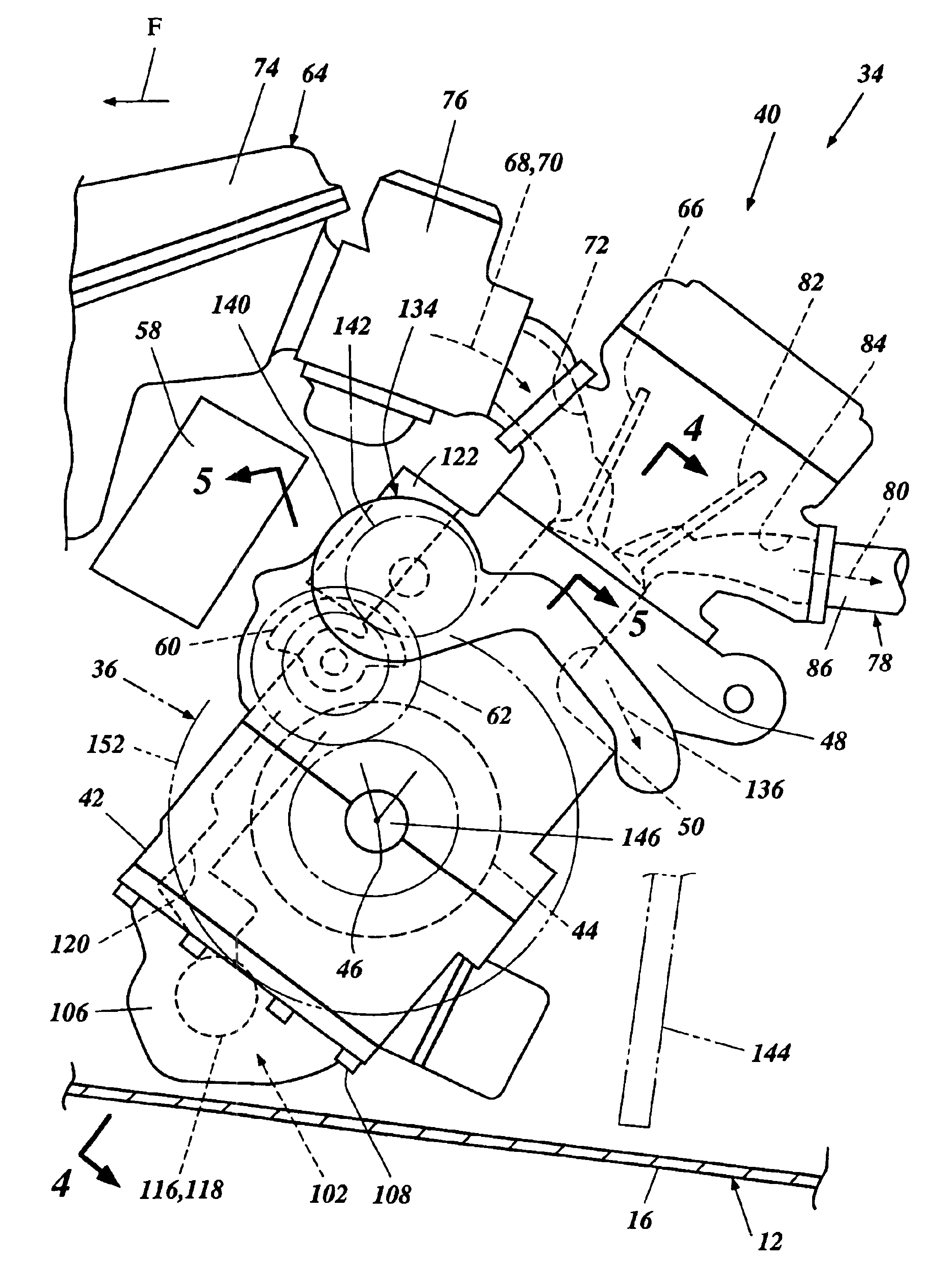
[0010]Accordingly, an improved snowmobile component layout providing improved stability and ride comfort of the snowmobile is provided by at least one of the inventions disclosed herein. Preferably, preferred embodiments of the present component arrangement lower the center of gravity of the snowmobile and provides improved traction of the drive assembly. In addition, preferably the component arrangement places the components of the snowmobile in a compact manner without impairing the function of the components.

Problems solved by technology

Most prior snowmobile component arrangements have resulted in less than optimal handling characteristics.
For example, prior component arrangements have resulted in the snowmobile having a center of gravity positioned too far forward and / or a center of gravity positioned too high relative to the body of the snowmobile, resulting in inadequate grip of the drive assembly with the ground surface and / or instability during turns or other lateral movements.

Method used


Image

  • Component arrangement for snowmobile
  • Component arrangement for snowmobile
  • Component arrangement for snowmobile

Examples


Embodiment Construction

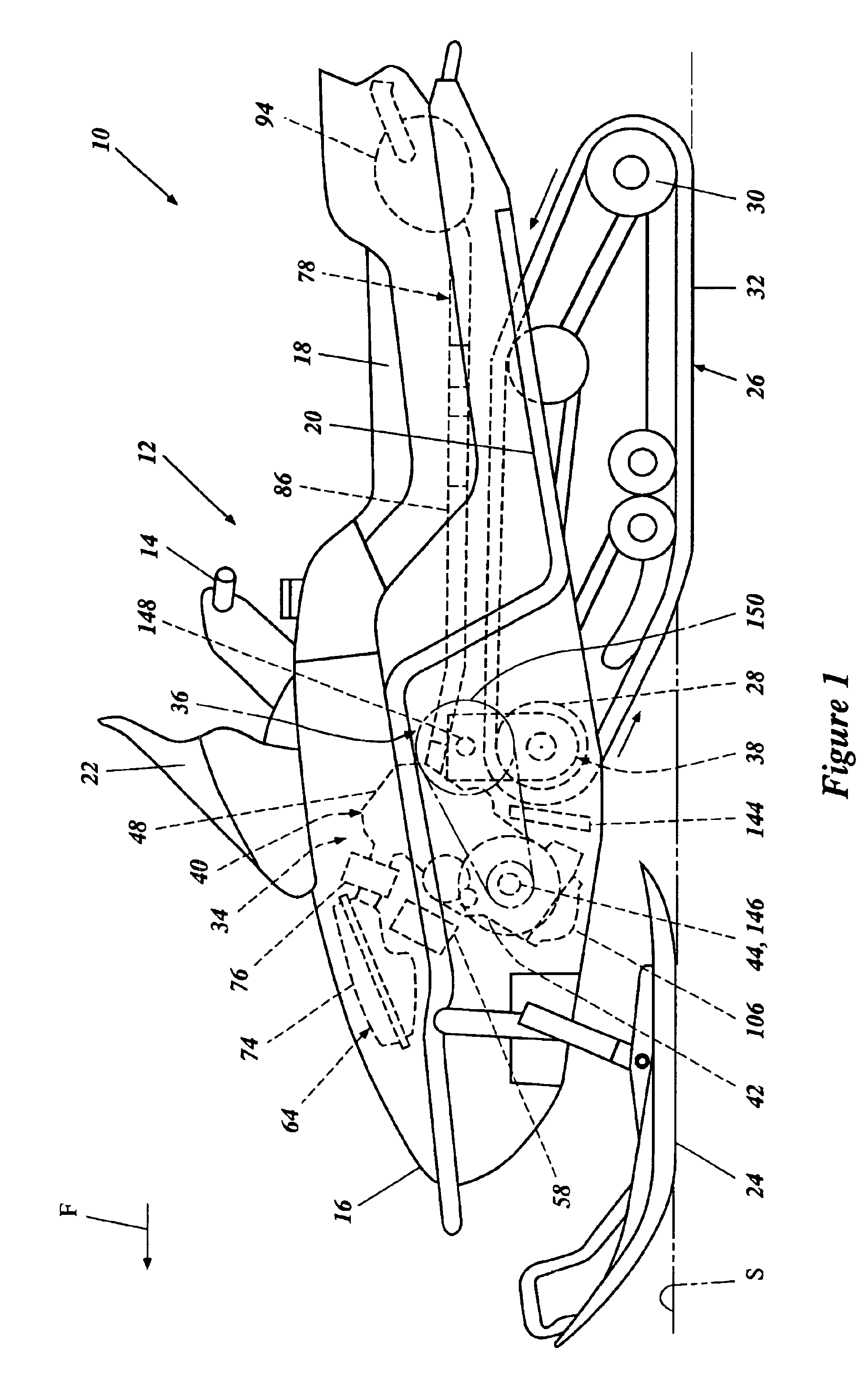
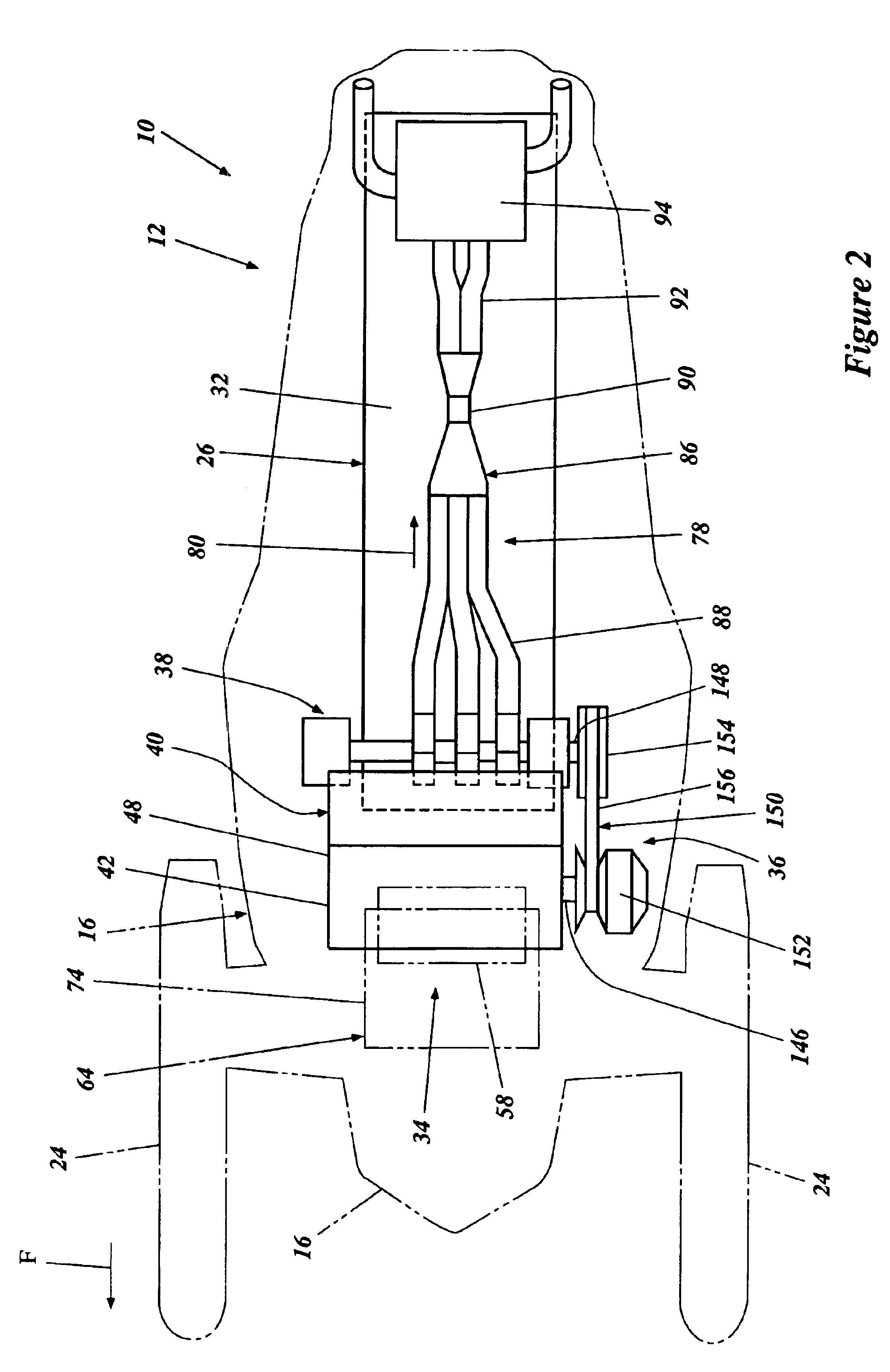
[0021]With reference to FIG. 1, a snowmobile incorporating a preferred embodiment of the present component arrangement is shown, and is generally referred to by the reference numeral 10. Although illustrated in connection with a snowmobile 10, the present component arrangement advantageously provides a compact engine arrangement, which can be adapted for utilization with other vehicles as well.

[0022]The snowmobile 10 is described in general detail in order to assist the reader's understanding of a preferred environment of use. The snowmobile 10 is described in relation to a coordinate system wherein a longitudinal axis extends along a length of the snowmobile 10. A vertical, central plane generally bisects the snowmobile 10 and contains the longitudinal axis. A lateral plane is oriented normal to the central plane. Relative heights are expressed as distances from a ground surface S upon which the snowmobile 10 operates. Right and left directions are given from the perspective of an ...


PUM


Abstract

A snowmobile including a frame assembly and a drive assembly coupled to the frame assembly. The drive assembly including a drive belt adapted to contact a ground surface to propel the snowmobile over the ground surface. An engine is supported by the frame assembly and includes an engine body. The engine body includes a crankcase, a crankshaft rotatably journaled within the crankcase for rotation about a crankshaft axis, and a cylinder block assembly extending in an upward direction from the crankcase. The cylinder block assembly defines at least one cylinder bore adapted to support a piston for a reciprocal motion along a bore axis. A balancer shaft is rotatably coupled to the crankshaft and supported by the engine body for rotation about a balancer shaft axis. The cylinder assembly is canted such that the bore axis is inclined to rearwardly from a vertical axis and the balancer shaft axis is disposed above the crankshaft axis. At least a portion of the balancer shaft can be disposed directly above the crankshaft.

Description

RELATED APPLICATION[0001]This application is related to, and claims priority from, Japanese Patent Application No. 2002-246408, filed Aug. 27, 2002, the entirety of which is expressly incorporated by reference herein.BACKGROUND OF THE INVENTION[0002]1. Field of the Invention[0003]The present invention relates generally to a snowmobile and, more particularly, to an improved component arrangement of a snowmobile.[0004]2. Description of the Related Art[0005]A conventional snowmobile includes an elongated body having a straddle-type seat extending along a rearward portion thereof to support an operator and one or more passengers of the snowmobile. A front end of the body is supported above the ground by one or more ski members and a rear end of the body is supported by a belt-type drive assembly. An engine is supported by the snowmobile body and is drivingly connected to the drive assembly to propel the snowmobile along the ground. In addition, suspension assemblies can be interposed be...

Claims


Application Information

Patent Timeline
IPC IPC(8): B62M27/02B62M27/00B60K5/02F02B77/00B62K27/02F01P5/10F02B67/00F02F7/00F02M35/16F16F15/26
CPCB60K5/02B62M27/02B62M2027/023
Inventor YAMAMOTO, MASANOBU
Owner YAMAHA MOTOR CO LTD
Learn More