Detachable arm limiting assembly

Inactive Publication Date: 2005-04-19
CALDWELL MFG NORTH AMERICA
View PDF15 Cites 15 Cited by
  • Summary
  • Abstract
  • Description
  • Claims
  • Application Information

AI Technical Summary

Benefits of technology

[0007]When the locking plate is secured to the mounting bracket, the degree to which the vent can be opened is limited. However, all that is required to allow the vent to be fully opened for cleaning or other maintenance is the loosening of the fastener, which allows the locking plate and the mounting plate to be moved from the second engaged position, to the first position, thus allowing ready disengagement of the arm from the mounting bracket. The present assembly has the advantage that while it is normally impractical to open of the vent beyond a selected limit, upon releasing the fastener the vent can quickly and easily be opened beyond this limit by a person having the appropriate tool for loosening the fastener.

Problems solved by technology

When the locking plate is secured to the mounting bracket, the degree to which the vent can be opened is limited.

Method used


Image

  • Detachable arm limiting assembly
  • Detachable arm limiting assembly
  • Detachable arm limiting assembly

Examples


Embodiment Construction

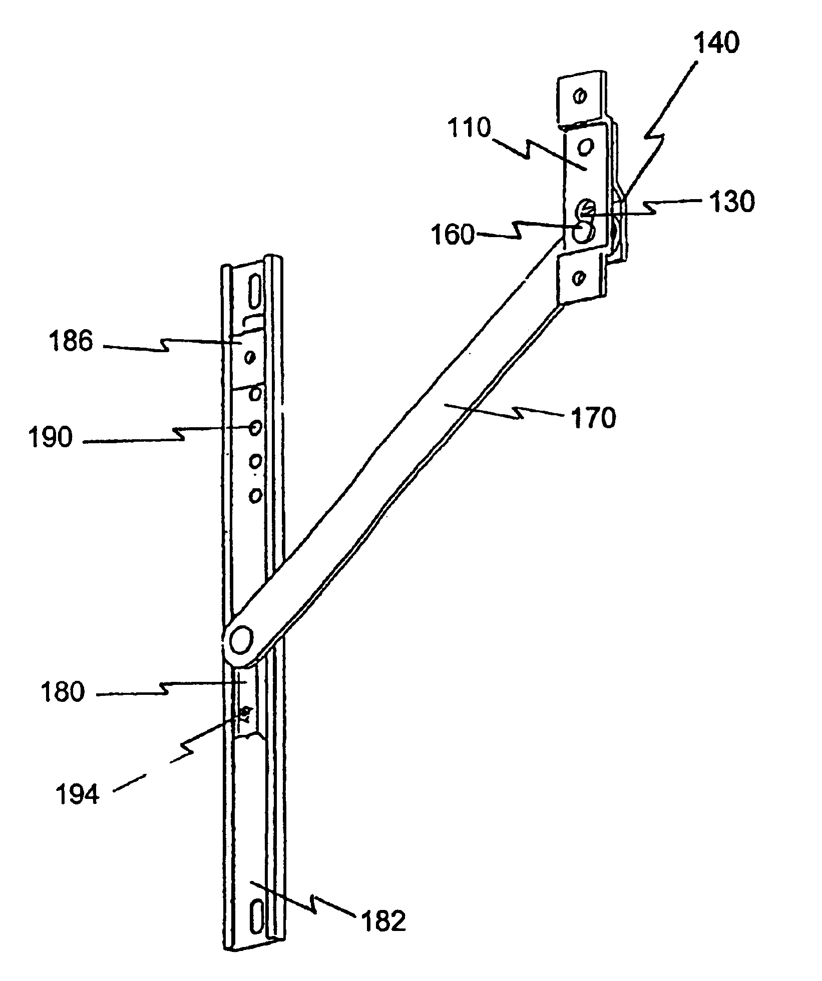
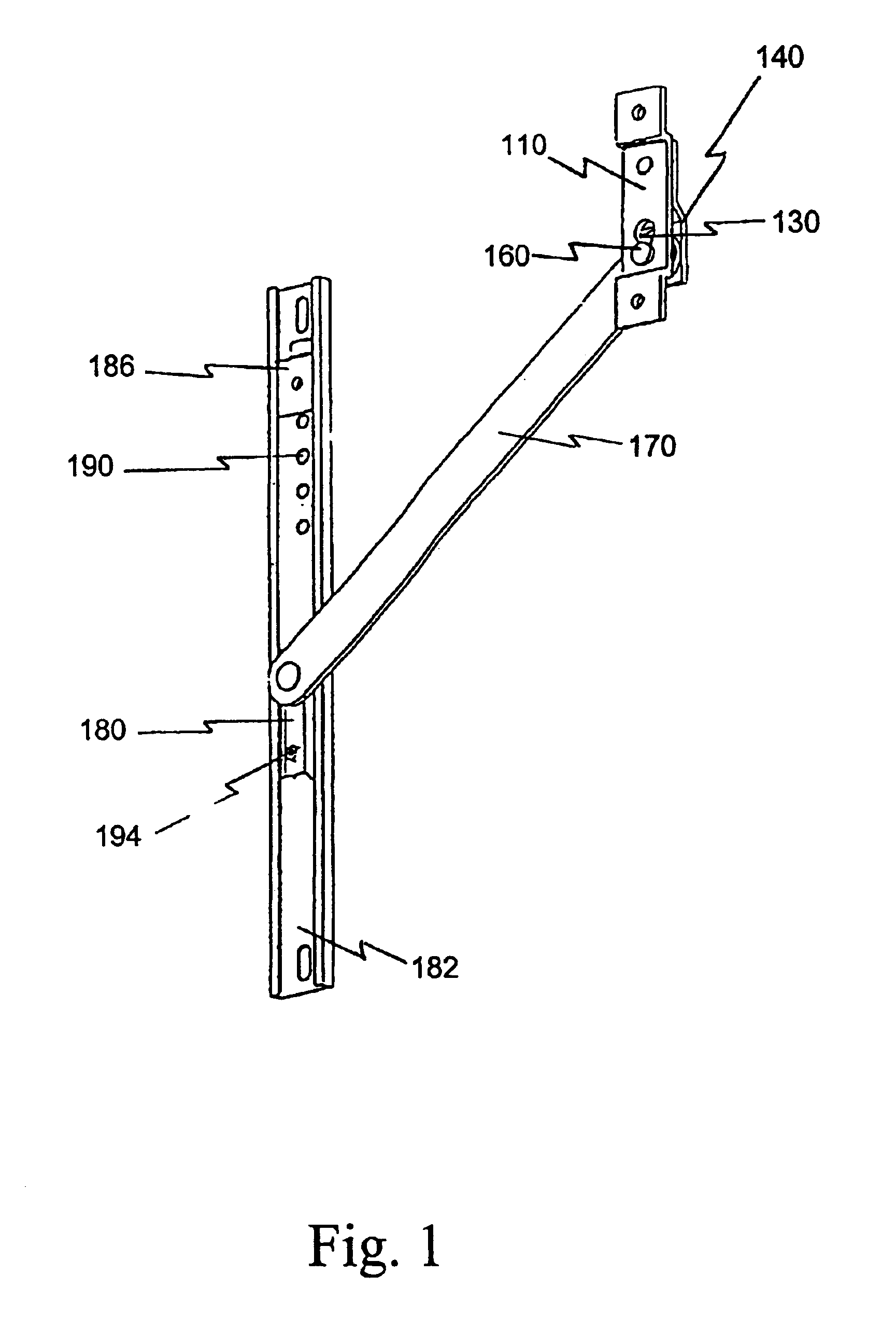
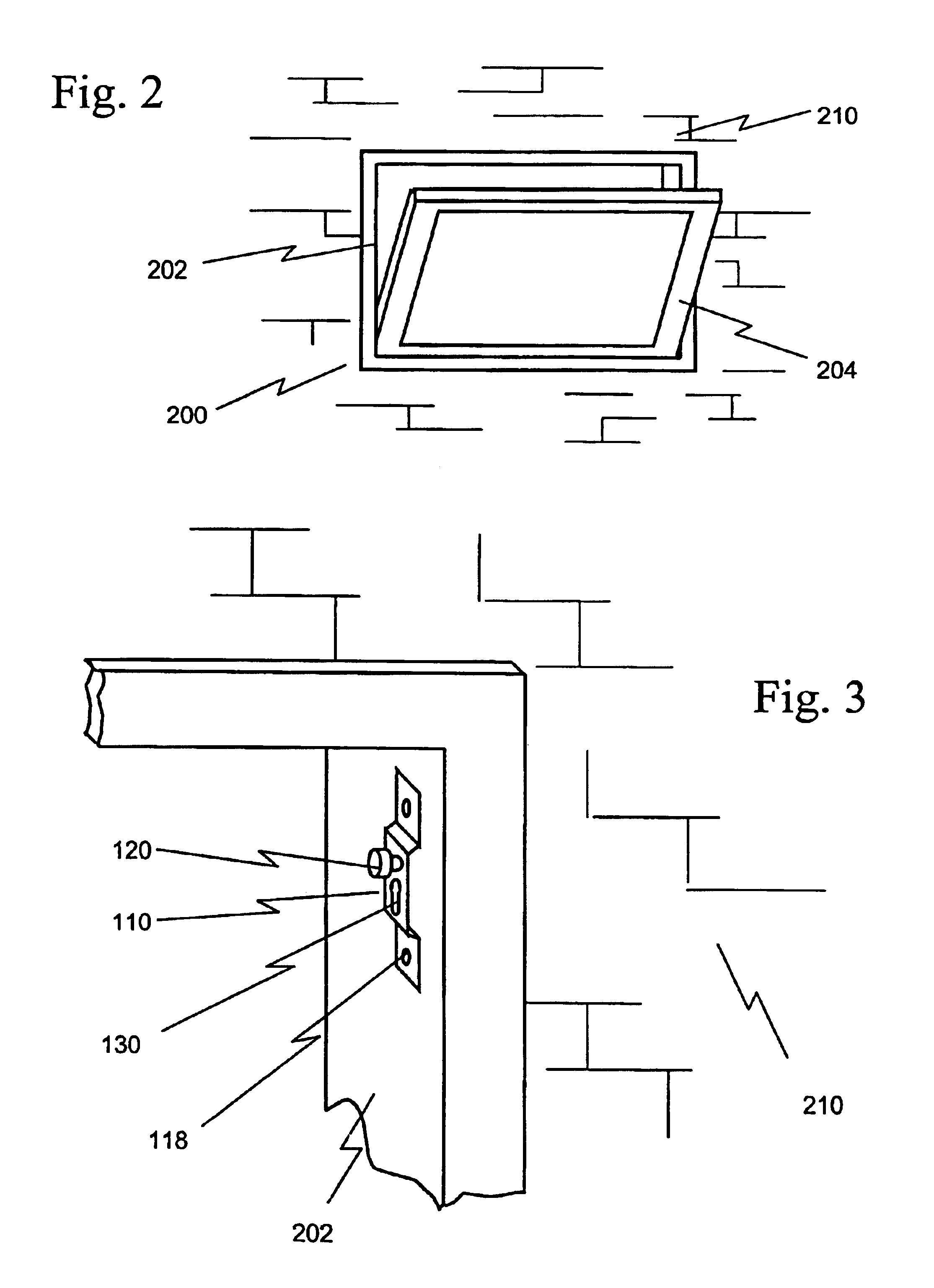
[0022]Referring now to the drawings, FIGS. 1 and 2 show a preferred embodiment of a detachable arm limiting assembly 100, which is used to limit the opening of a window 200. The window moves relative to a frame 202 which is normally set into a building wall 210. The window is connected to a vent 204. The assembly 100 restricts the travel of the vent 204 relative to the frame 202. The vent 204 is typically rectangular in shape and engages the frame 202 through a conventional hinge mechanism such as a 4 bar hinge 206. The hinge 206 provides that the vent 204 can pivot about a horizontal axis. As indicated in FIG. 2, the vent is disposed so that it opens downward into the building. However, it is understood the axis about which the vent rotates can be horizontal, vertical or an intermediate orientation.

[0023]FIGS. 4 and 5 show the general disposition of the assembly 100 with the frame 202 and vent 204. FIG. 4 shows the attachment of the assembly 100 and the hinge mechanism 206 to the f...


PUM


Abstract

A mechanism which selectably limits the opening of a hinged window vent. The mechanism has a releasable arm that permits the vent to be conveniently opened beyond the selected limit. An assembly is disclosed for limiting travel of a vent relative to a frame. The assembly includes a security fastener for restricting transition of the assembly between a locked configuration and an unlocked configuration. An arm is pivotally connected to a mounting bracket by a locking plate and a loading pin.

Description

FIELD OF THE INVENTION[0001]This invention relates to a mechanism for limiting the travel of a hinged window in a frame, and in particular to an assembly that is releasably and securely fastened to the window and the frame.BACKGROUND OF THE INVENTION[0002]A common type of window includes a rectangular frame set into a building wall and a corresponding vent connected to the frame by a hinge assembly. The hinge assembly can be oriented so that the vent can pivot about either a horizontal or a vertical axis. Thus, the vent can be opened by pivoting inward and downward about a horizontal axis. Various means are available for securing the vent at a selectable angle to make the opening larger or smaller. It is often desirable to limit the size of the opening; for example, the window might be located in a school, where it is clearly preferable that the opening not be large enough to permit unauthorized, unintended or accidental entry or exit. Prior hinge assemblies include limit mechanisms...

Claims


Application Information

Patent Timeline
IPC IPC(8): E05C17/00E05C17/04E05C17/24
CPCE05C17/045E05C17/24
Inventor MUIR, MALCOLM
Owner CALDWELL MFG NORTH AMERICA
Why Eureka
Try Eureka