Remaining lifetime estimating method, temperature detecting structure and electronic equipment

a lifetime estimation and estimating method technology, applied in capacitor manufacturing, emergency protective arrangements responsive to undesired changes, instruments, etc., can solve the problems of inability to easily use the day, conventional techniques cannot inform the lifetime at the time of actual use, and the conventional technique canno

Inactive Publication Date: 2005-04-19
ORMON CORP
View PDF11 Cites 53 Cited by
  • Summary
  • Abstract
  • Description
  • Claims
  • Application Information

AI Technical Summary

Benefits of technology

[0052]According to the present invention, the indication manner of the calculated remaining lifetime is not limited to the numerical value indication on the basis of years, months, or hours, and it is possible t

Problems solved by technology

Therefore, the conventional technique can not inform a lifetime at the time of actual use.
Therefore, the conventional technique in which an alarm informing that the electronic equipment is at the end of the lifetime is output or indicated suddenly one day can not be used easily.
If the alarm informing that the equipment is at the end of the lifetime is output or indicated on a day other than a periodical maintenance term, there is a problem that the line

Method used


Image

  • Remaining lifetime estimating method, temperature detecting structure and electronic equipment
  • Remaining lifetime estimating method, temperature detecting structure and electronic equipment
  • Remaining lifetime estimating method, temperature detecting structure and electronic equipment

Examples


Embodiment Construction

[0062]An embodiment of the present invention will be explained below based on the drawings.

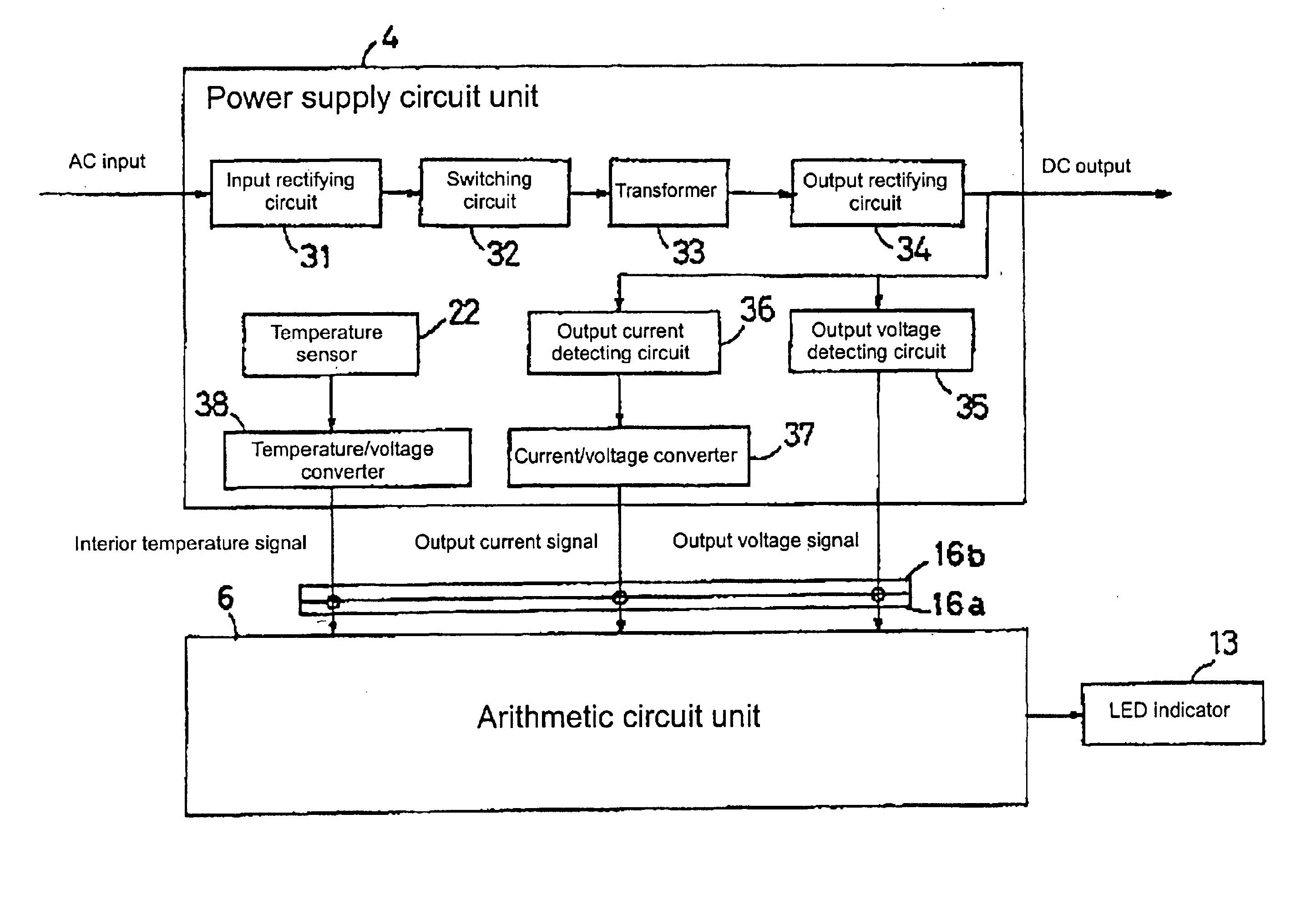
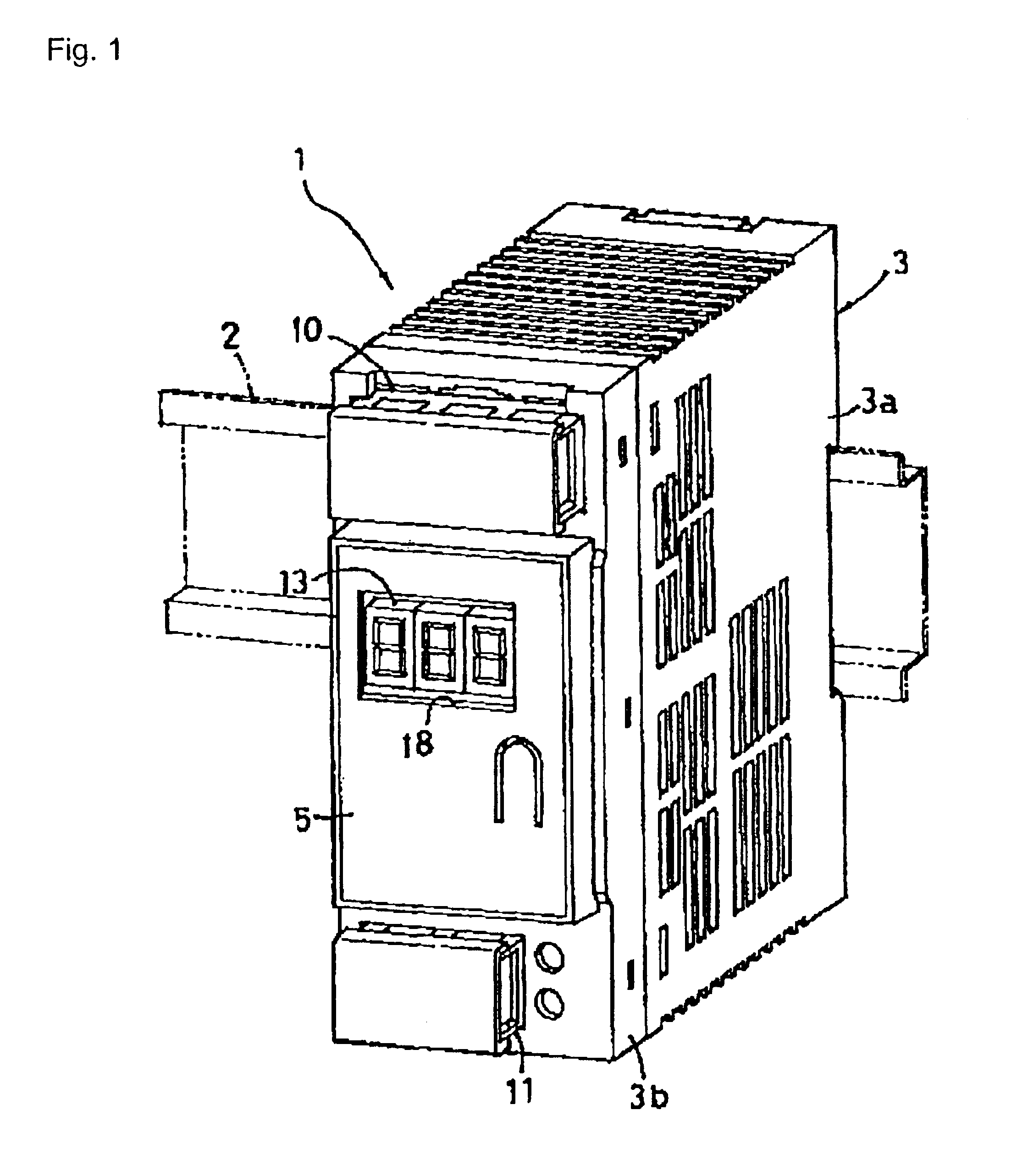
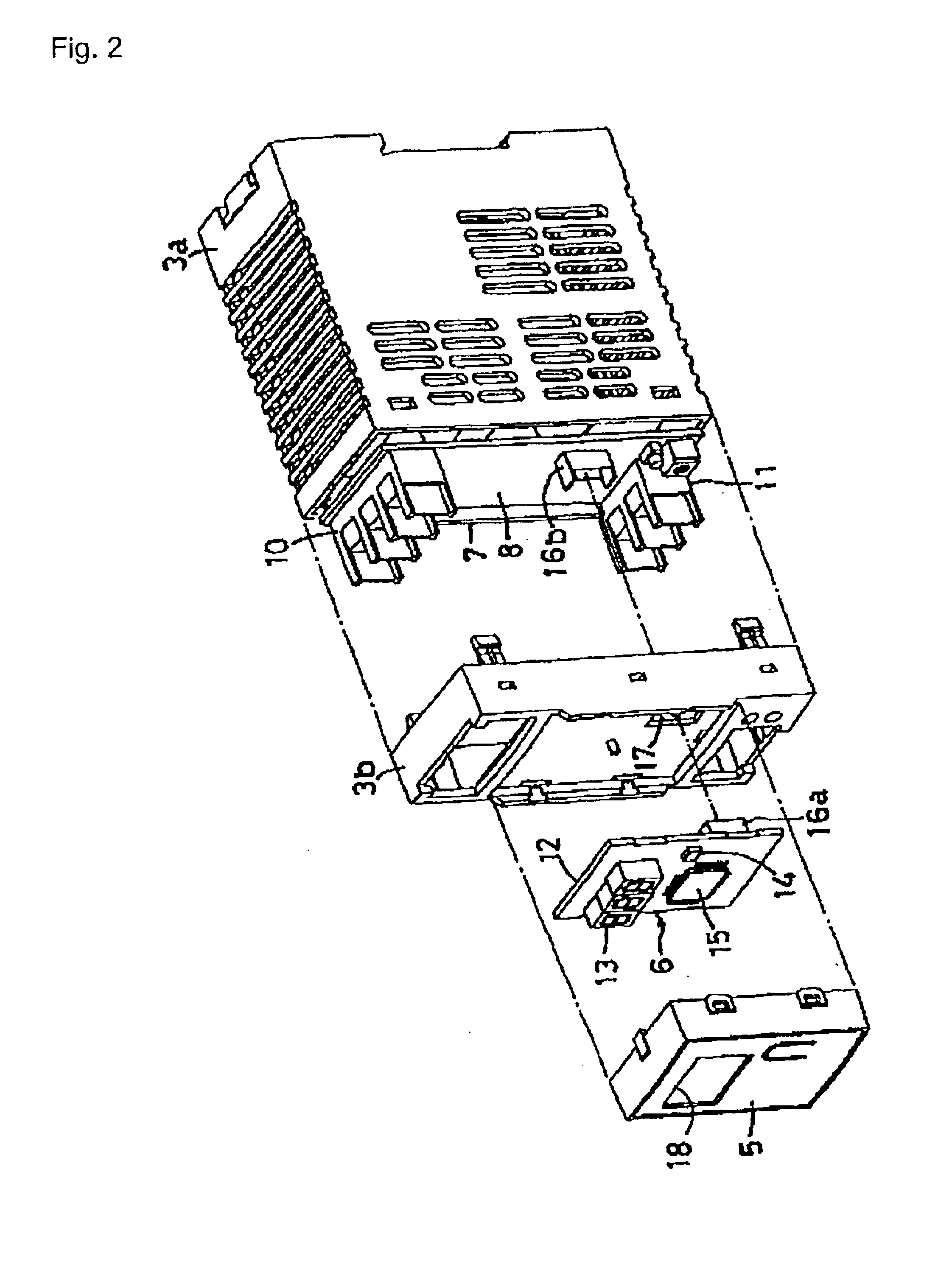
[0063]FIG. 1 is a perspective view of an entire power supply unit according to the present invention. FIGS. 2 and 3 are exploded perspective views thereof. FIG. 4 is a plan view partly in section thereof.

[0064]This power supply unit 1 is formed into a box-like unit which is detachably mounted on a front surface a supporting rail 2 such as a DIN rail. The supporting rail 2 is laterally fix to power supply equipment. A casing 3 of the power supply unit 1 comprises a box-like resin case body 3a and a resin front cover 3b. The case body 3a has a large horizontal depth, its front surface is opened. The front cover 3b is engaged with and connected to the front surface. A power supply circuit unit 4 shown in FIG. 3 is incorporated and supported in the casing 3.

[0065]A shallow box-like resin auxiliary case 5 whose rear surface is opened is detachably engaged with and connected to the front surface of ...


PUM


Abstract

A temperature of an electrolytic capacitor 24 incorporated in equipment is detected, a remaining lifetime in actual use is calculated based on a temperature-lifetime law, and the remaining lifetime is indicated. A thin film tape 23 is wound around a temperature sensor 22 for insulation, and the electrolytic capacitor 24 and the temperature sensor 22 are accommodated in a heat-shrinkable tube 25, the secondary temperature sensor 22 is brought into tight contact with the primary electrolytic capacitor 24.

Description

BACKGROUND OF THE INVENTION[0001]1. Field of the Invention[0002]The present invention relates to a method for estimating a remaining lifetime of a capacitor and the like, a temperature detecting structure suitable for the method, and various electronic equipment such as a power supply unit having such a capacitor.[0003]2. Description of the Background Art[0004]In electronic equipment of this kind, for example, a power supply unit, a lifetime of an electrolytic capacitor having the shortest lifetime among circuit components used for the power supply unit is estimated as a lifetime of the power supply unit.[0005]It is known that the lifetime of the electrolytic capacitor can be calculated by the following arithmetic expression based on the Arrhenius law which is a law of temperature-lifetime showing a relation between a temperature and a lifetime:Lx=Lo×2(To−tx) / 10×k[0006]Lx: estimated lifetime at the time of actual use (time)[0007]Lo: warranty lifetime (time) at a maximum using temper...

Claims


Application Information

Patent Timeline
IPC IPC(8): G01K3/00G01K3/04G01K7/00H01G9/00H01G13/00H02M3/28
CPCG01K3/04G01R31/028G01R31/003G01R31/64H02H6/00
Inventor ISOZUMI, MASASHIOBA, TSUNETOSHI
Owner ORMON CORP
Why Eureka
Try Eureka