Reciprocating compressor having reduced vibration

a compressor and vibration reduction technology, applied in the direction of positive displacement liquid engine, pump components, piston pumps, etc., can solve the problems of fixed scroll, difficult to process orbital scrolls b>, complicated structure, etc., to minimize vibration noise generated in operation, accurate control of compressed gas amoun

Inactive Publication Date: 2005-04-19
LG ELECTRONICS INC
View PDF11 Cites 35 Cited by
  • Summary
  • Abstract
  • Description
  • Claims
  • Application Information

AI Technical Summary

Benefits of technology

[0019]Therefore, it is an object of the present invention to provide a reciprocating compressor that is capable of accurately controlling the amount of a compressed gas to be discharged as well as minimizing a vibration noise generated in operation.
[0020]Another object of the present invention is to provide a reciprocating compressor that is capable of simplifying assembly of components and minimizing an assembly tolerance.

Problems solved by technology

Referring to the reciprocating compressor, in its structural aspect, the balance weight 13b is used for a rotational balance between the crank shaft 13 having an eccentric part 13a, the piston 14 coupled to the crank shaft 13 and the crank shaft eccentric part 13a, resulting in that there are numerous components and its structure is complicated.
In addition, it is difficult to process the orbital scroll 24 and the fixed scroll 25.
Thus, in order to control the amount of the compressed gas generated in the compressor, the number of rotations of the electronic mechanism unit should be reduced or the electronic mechanism unit should stop rotating, which makes it difficult to accurately control the amount of the compressed gas.
In addition, since the eccentric parts 3a, 13a and 23a are provided at the shaft which is rotated upon receipt of the rotational force from the electronic mechanism unit, the balance weights 6, 13b and 26 are used, causing that a driving force is much consumed, and as the vibration noise is generated in operation, its reliability is degraded.
In addition, since the structure is relatively complicate, the assembly productivity is degraded.

Method used


Image

  • Reciprocating compressor having reduced vibration
  • Reciprocating compressor having reduced vibration
  • Reciprocating compressor having reduced vibration

Examples


first embodiment

[0038]FIG. 4 is a sectional view showing a reciprocating compressor in accordance with the present invention.

[0039]As shown in FIG. 4, the reciprocating compressor includes a container 100 communicating with a gas suction pipe 110 for sucking a gas, a reciprocating motor 200 installed in the container 100, for generating a linear reciprocal driving force; a compression unit 300 positioned inside the reciprocating motor 200, for receiving the linear reciprocal driving force of the reciprocating motor 200 and compressing a gas; a suction unit 400 positioned at one side of the compression unit 300, for rendering the gas sucked into the container 100 through the gas suction pipe 110 due to the pressure difference in the compression unit 300 to be sucked into the compression unit 300; a discharge unit 500 positioned at the other side of the compression unit 300, for discharging the gas compressed in the compression unit 300 to the outside of the container 100; a resonance spring unit 600...

second embodiment

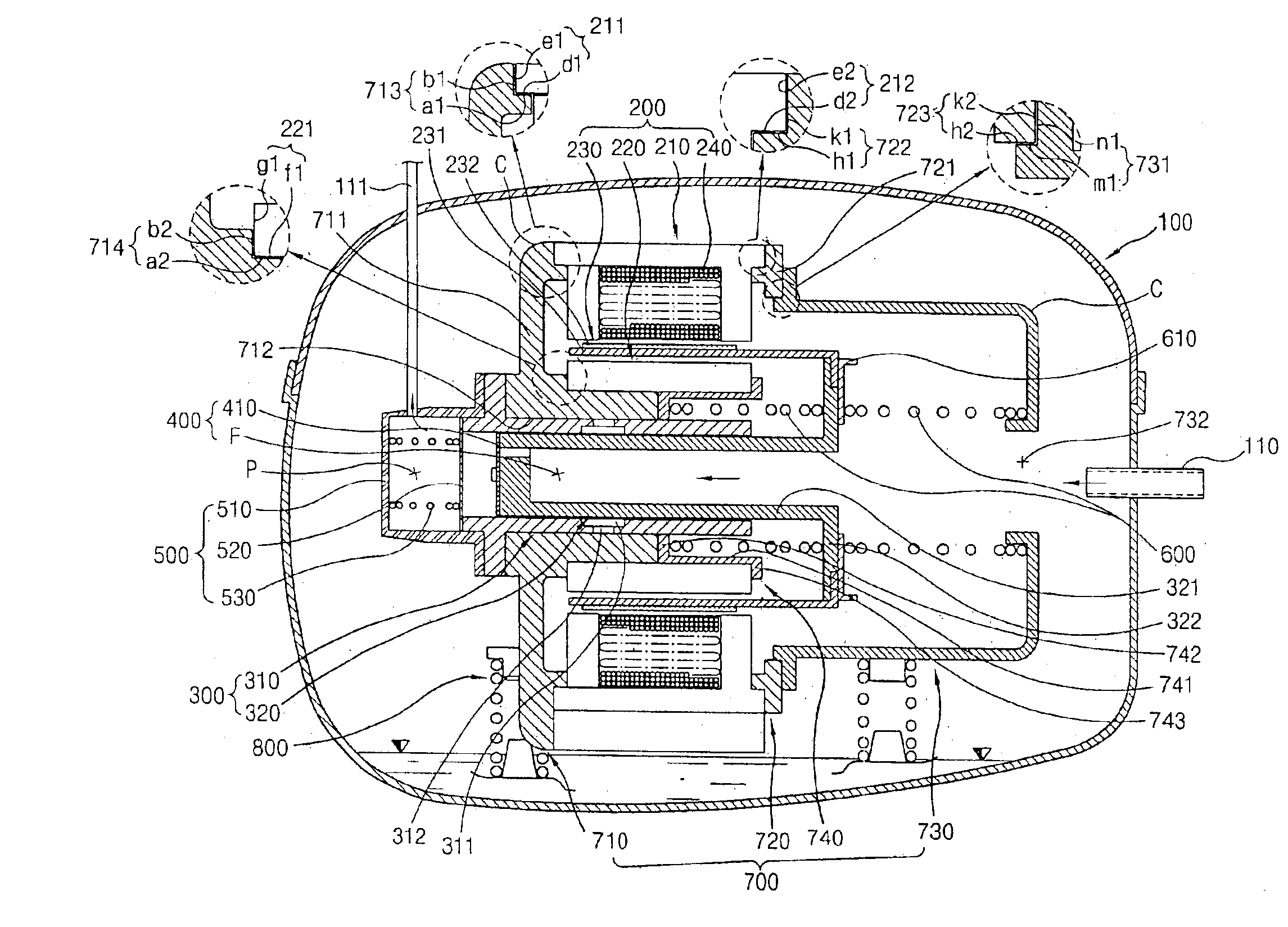
[0107]FIG. 10 is a sectional view showing a reciprocating compressor in accordance with the present invention, in which a compression unit 300 and a reciprocating motor 200 are positioned with a predetermined interval therebetween.

[0108]The reciprocal compressor in accordance with the second embodiment of the present invention includes a container 100 provided with a gas suction pipe 110 through which a gas is sucked; a frame unit 700 installed inside the container 100, a reciprocating motor 200 mounted at the frame unit 700, for generating a linear and reciprocal driving force; a compression unit 300 mounted at the frame unit 700 at a predetermined interval from the reciprocating motor 200, for receiving the driving force of the reciprocating motor 200 and compressing a gas; a resonance spring unit 600 for elastically supporting the linear and reciprocal driving force of the reciprocating motor 200; a suction unit 400 positioned at one side of the compression unit 300, for renderin...


PUM


Abstract

A reciprocating compressor includes: a reciprocating motor, an outer stator and an inner stator provided with at least one step portion at both sides thereof, and an armature linearly moving therebetween; a compression unit having a cylinder and a piston inserted in the cylinder to receive a linear and reciprocal driving force of the reciprocating motor and compress a gas; a suction unit sucking a gas into the compression unit; a discharge unit discharging the gas compressed in the compression unit to outside the container; a resonance spring unit elastically supporting the piston and the armature; and a frame unit supporting the compression unit and the reciprocating motor. Because stable driving is achieved in its operation, generation of vibration and noise can be minimized, heightening reliability. In addition, the amount of gas discharge can be accurately controlled.

Description

[0001]This application is the national phase under 35 U.S.C. § 371 of PCT International Application No. PCT / KR01 / 00877 which has an International filing date of May 25, 2001, which designated the United States of America.TECHNICAL FIELD[0002]The present invention relates to a reciprocating compressor that is capable of minimizing a vibration noise occurring in operation, accurately controlling the amount of a compressed gas to be discharged, simplifying assembly of a construction components, and minimizing the assembly tolerance.BACKGROUND ART[0003]In general, a compressor is an instrument to compress a gas such as a coolant. There are several types of compressors including a rotary compressor, a reciprocating compressor, a scroll compressor.[0004]The general compressor includes a closed container having a space therein, an electronic mechanism unit installed inside the closed container and generating a driving force, and a compression mechanism unit for receiving the driving force ...

Claims


Application Information

Patent Timeline
Patent Type & Authority Patents(United States)
IPC IPC(8): F04B39/00F04B35/00F04B35/04F04B39/14F04B39/12
CPCF04B35/045F04B39/14F04B39/0027
Inventor HEO, JONG-TAEHYEON, SEONG-YEOLHUR, KYUNG-BUMBAE, GYOO-JONGKIM, JANG-WHAN
Owner LG ELECTRONICS INC
Why Eureka
Try Eureka