Enhanced fault protection in electricity meter

a technology of fault protection and electricity meter, which is applied in the field of fault protection in electricity meters, can solve the problem that the power follower of phase to phase short circuits is not as high as the current provided

Active Publication Date: 2005-04-19
LANDIS GYR LLC
View PDF2 Cites 33 Cited by
  • Summary
  • Abstract
  • Description
  • Claims
  • Application Information

AI Technical Summary

Problems solved by technology

In particular, if a line surge and / or other phenomenon causes a phase to phase arc, the phase to phase short circuit does not provide as high a current for power follow through because the series impedance limits the current through the phase to phase circuit.

Method used


Image

  • Enhanced fault protection in electricity meter
  • Enhanced fault protection in electricity meter
  • Enhanced fault protection in electricity meter

Examples


Embodiment Construction

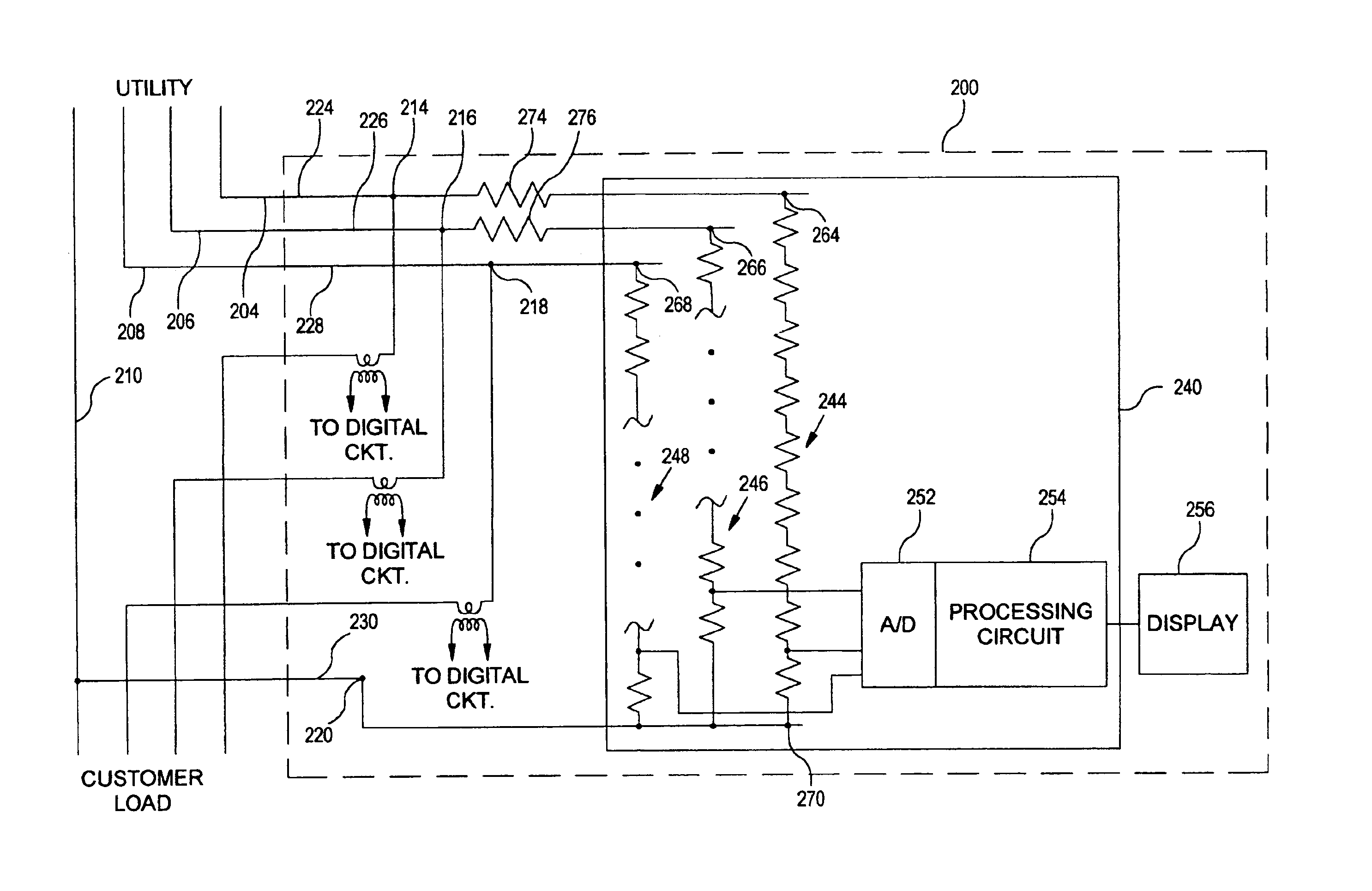
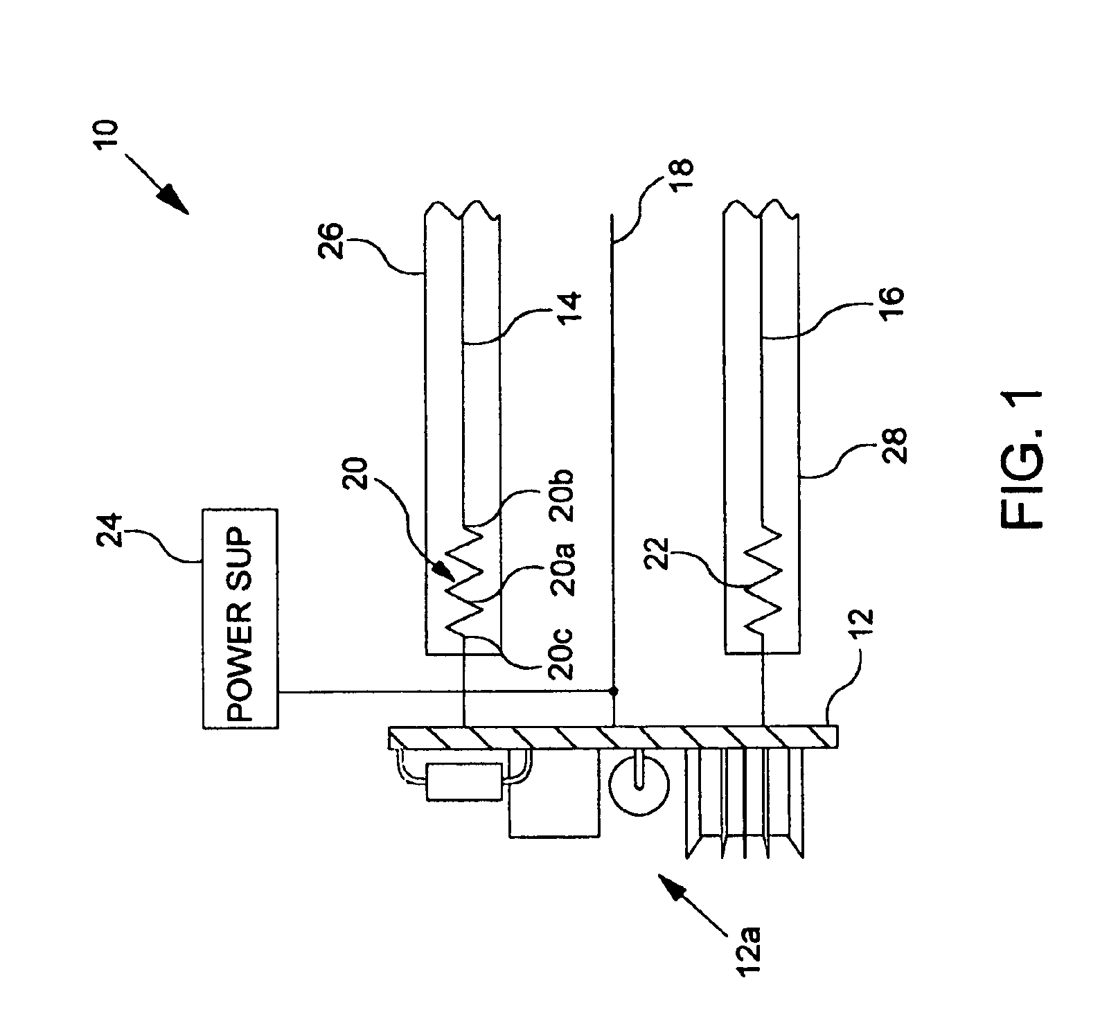
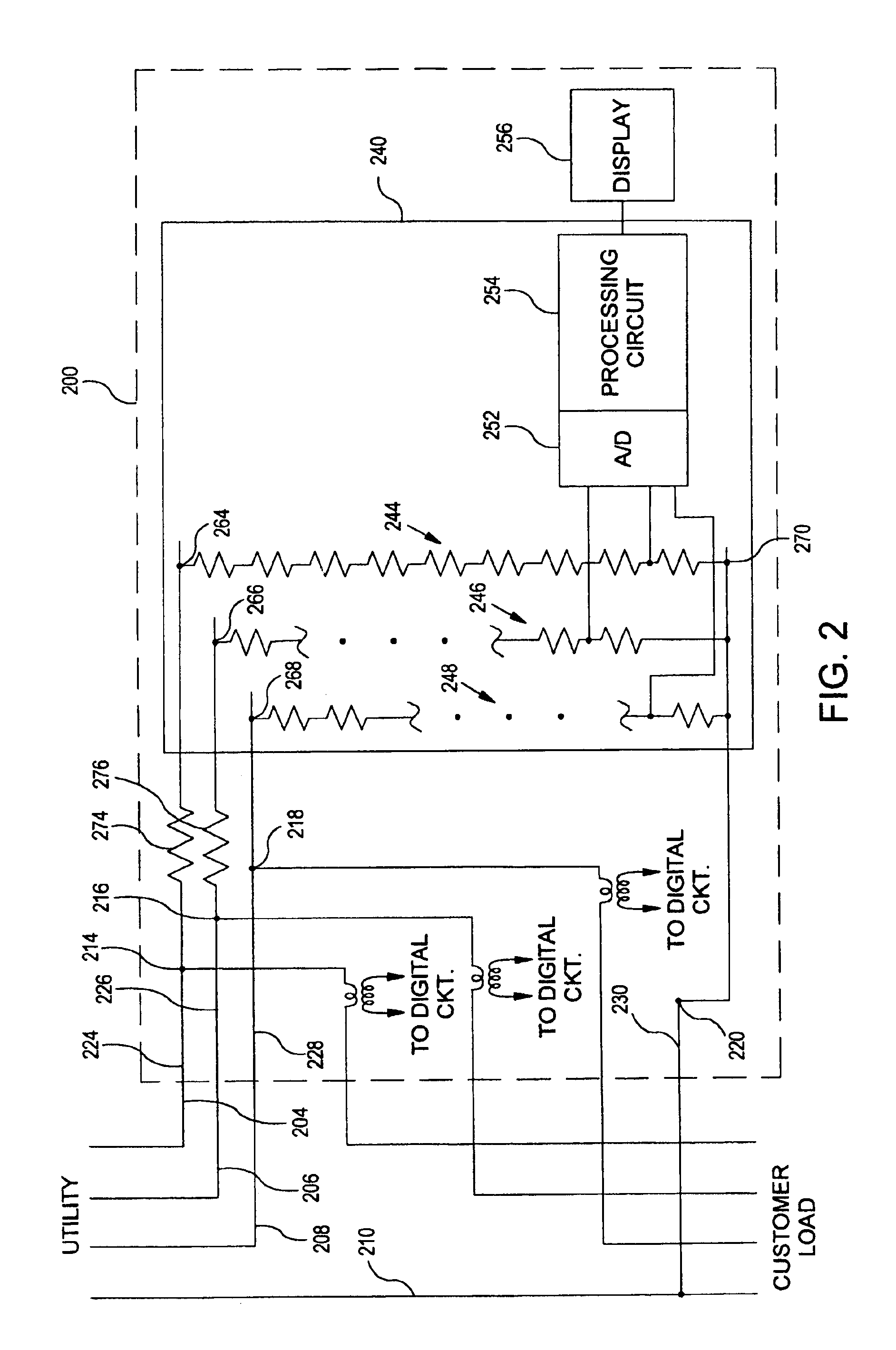
[0020]FIGS. 1 and 2 show implementations of the invention. FIG. 1 shows a part schematic, part plan view of a first exemplary embodiment of an arrangement 10 for use in a polyphase electricity meter according to the invention. The arrangement 10 includes a measurement circuit board 12 on which is disposed a measurement circuit 12a, a phase A line connection 14, a phase B line connection 16 and a phase C line connection 18. The arrangement 10 further includes a first impedance 20 disposed in series between the phase A line connection and the measurement circuit board 12, and a second impedance 22 disposed in series between the phase B line connection and the measurement circuit board 12. The phase C line connection 18 is connected directly to the measurement circuit board 12, and to a power supply 24 which may or may not be disposed on the measurement circuit board 12. A line connection is a connection to the high voltage provided by the mains electrical lines.

[0021]The measurement c...


PUM


Abstract

An arrangement for obtaining measurable voltage signals in a utility meter wherein the measurable voltage signals are representative of a power line voltage signal. Includes a first connection to a phase of a power line, a second connection to a reference of a power line, a voltage divider circuit, and a series impedance element. The voltage divider circuit is disposed on a circuit board and is coupled between a first node and the second connection. The voltage divider circuit has an output configured to provide measurable voltage signals to a circuit operable to generate voltage measurement information. The voltage divider circuit has a first impedance value. The series impedance element is disposed apart from the circuit board and is configured for current limiting. The series impedance element is coupled between the first connection and the first node and has a second impedance value.

Description

[0001]This application claims the benefit of U.S. Provisional patent Application Ser. No. 60 / 431,170, filed Dec. 5, 2002, which is incorporated herein by reference.FIELD OF THE INVENTION[0002]The present invention relates generally to electricity meters, and more particularly, to fault protection in electricity meters.BACKGROUND OF THE INVENTION[0003]Electricity meters are devices that perform measurements related to power and energy consumption. For example, electricity meters may be used to measure energy consumption by a customer load. Electricity meters also measure other properties relating to energy consumption such as voltage levels, current levels, and power factor by way of example. Utility service providers employ electricity meters to track customer usage for many purposes, including billing, planning and tracking demand for electrical power.[0004]Historically, electricity meters employed electromechanical “rotating disk” meters that measured energy consumption using magn...

Claims


Application Information

Patent Timeline
Patent Type & Authority Patents(United States)
IPC IPC(8): G01R11/00G01R11/04G01R22/06G01R22/10
CPCG01R22/10G01R22/065
Inventor VOISINE, JOHN T.
Owner LANDIS GYR LLC
Why Eureka
Try Eureka