Rectifier type frequency doubler with harmonic cancellation

a frequency doubler and harmonic cancellation technology, applied in the field of frequency multiplier circuits, can solve the problems of substantial cancellation of unwanted output harmonics in output signals

Inactive Publication Date: 2005-04-19
CUFER ASSET LTD LLC
View PDF10 Cites 14 Cited by
  • Summary
  • Abstract
  • Description
  • Claims
  • Application Information

AI Technical Summary

Benefits of technology

[0011]In one embodiment, the invention can be characterized as a frequency doubler device comprising a first rectifier doubler stage adapted to receive a first input signal having a first frequency and adapted to output a first rectified signal having multiple harmonics; a second rectifier doubler stage adapted to receive a second input signal having the first frequency and offset in phase from the first input signal and adapted to output a second rectified signal, wherein the second rectified signal has the multiple harmonics and is offset in phase from the first rectified signal; and a differential amplifier stage coupled to the first rectifier doubler stage and the second rectifier doubler stage and adapted to sum the first rectified signal and the second rectified signal to produce an output signal. The output signal includes a desired output harmonic having a frequency that is double the first frequency. The summing results in the substantial cancellation of unwanted output harmonics in the output signal.

Problems solved by technology

The summing results in the substantial cancellation of unwanted output harmonics in the output signal.
The summing results in the substantially cancellation of unwanted output harmonics in the output signal.

Method used


Image

  • Rectifier type frequency doubler with harmonic cancellation
  • Rectifier type frequency doubler with harmonic cancellation
  • Rectifier type frequency doubler with harmonic cancellation

Examples


Embodiment Construction

[0029]The following description is not to be taken in a limiting sense, but is made merely for the purpose of describing the general principles of the invention. The scope of the invention should be determined with reference to the claims.

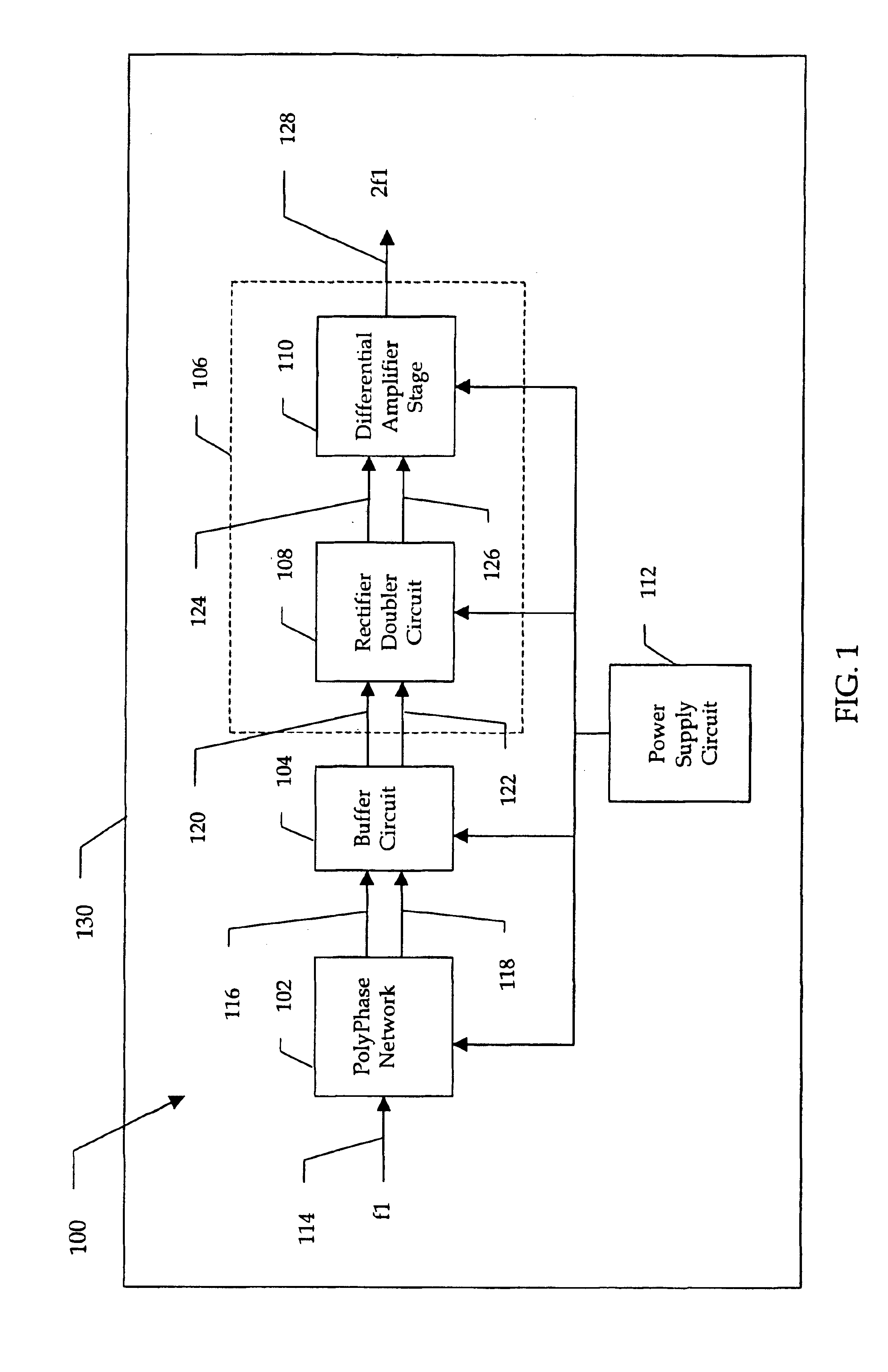
[0030]Generally an improved frequency multiplier circuit (e.g., a frequency doubler) is described with reference to FIGS. 1-6 while an improved polyphase network (e.g., for use in one embodiment of the improved frequency multiplier circuit) is described with reference to FIGS. 7A-11.

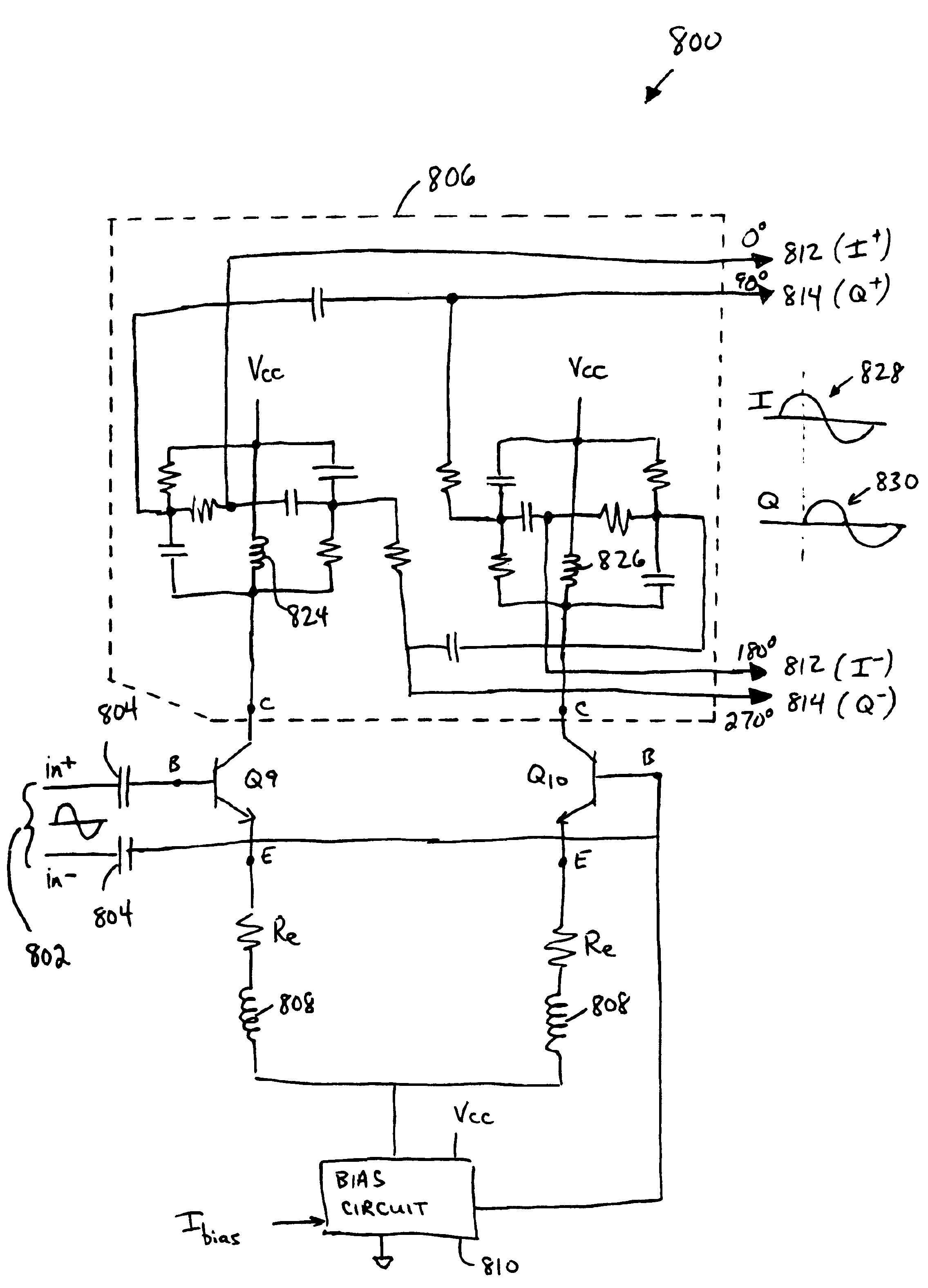
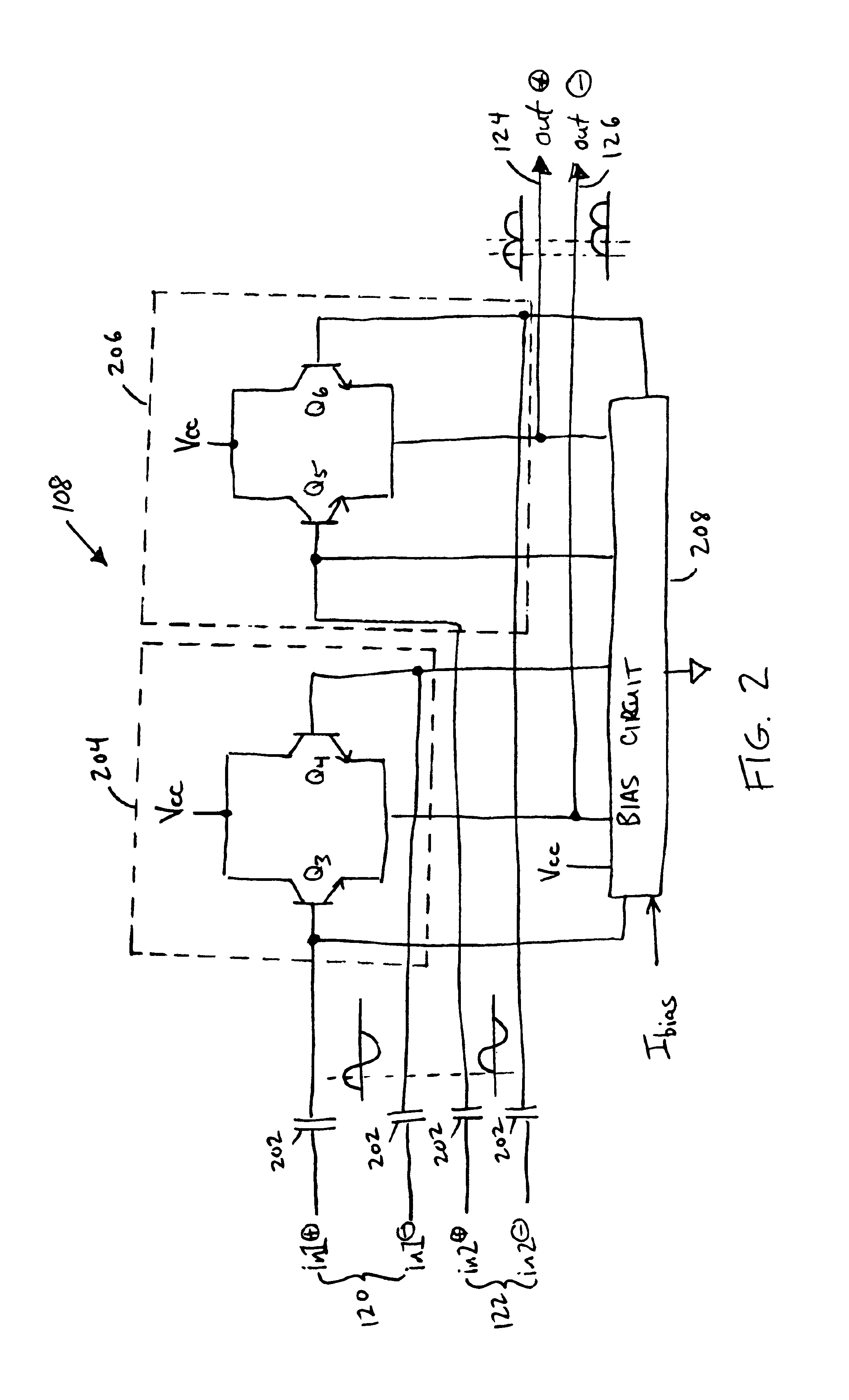
[0031]According to several embodiments of the invention, a frequency multiplier circuit is provided that does not require filtering for rejection. According to several embodiments, the input signal to be multiplied, e.g., doubled, is passed through a polyphase network, which produces two signals having the same frequency but offset in phase. Next, in a frequency doubler, each input signal is doubled using a known rectifier type doubler for each input signal, then the re...


PUM


Abstract

A frequency multiplier circuit is provided that does not rely on filtering to remove unwanted harmonics and spurious content. In one implementation, a frequency doubler comprises a first rectifier doubler stage adapted to receive a first input signal having a first frequency and output a first rectified signal having multiple harmonics; a second rectifier doubler stage adapted to receive a second input signal having the first frequency and offset in phase from the first input signal and to output a second rectified signal, which has the multiple harmonics and is offset in phase from the first rectified signal; and a differential amplifier stage adapted to sum the first and second rectified signals to produce an output signal including a desired output harmonic having a frequency that is double the first frequency. The summing results in the substantial cancellation of unwanted output harmonics in the output signal.

Description

[0001]This patent document relates to the following patent document filed concurrently herewith, which is incorporated herein by reference: U.S. patent application Ser. No. 10 / 602,364, of Kwok; entitled POLY-PHASE NETWORK WITH RESONANT CIRCUIT BANDPASS SHAPING.BACKGROUND OF THE INVENTION[0002]1. Field of the Invention[0003]The present invention relates generally to frequency multiplier circuits, and more specifically to frequency doubler circuits for producing a relatively pure output for use in radio equipment.[0004]2. Discussion of the Related Art[0005]In radio communications, in order to reduce the number of oscillators, it is desirable to multiply the frequency of a local oscillator to effectively derive another local oscillator. For example, a frequency doubler is a circuit that produces an output signal at the twice the frequency of the input signal, the input signal or fundamental frequency being suppressed from the output. Typically, frequency doubling is realized by feeding...

Claims


Application Information

Patent Timeline
Patent Type & Authority Patents(United States)
IPC IPC(8): H03D7/14H03B19/00
CPCH03B19/00H03D7/1433H03D7/1491H03D7/165H03D7/1458H03D2200/0047H03D2200/0086
Inventor KWOK, SAI
Owner CUFER ASSET LTD LLC
Why Eureka
Try Eureka