Pressure compensated hydrophone

a hydrophone and pressure compensation technology, applied in the field of hydrophones, can solve the problems of large production cost, large damage and collapse, and small effect, and achieve the effect of reducing production cost, reducing production cost, and reducing production cos

Inactive Publication Date: 2005-04-19
WEATHERFORD TECH HLDG LLC
View PDF14 Cites 35 Cited by
  • Summary
  • Abstract
  • Description
  • Claims
  • Application Information

AI Technical Summary

Problems solved by technology

While hydrostatic pressure has a measurable effect on a hydrophone, especially when the hydrophone is deployed at extreme depths, small dynamic pressures, such as propagating acoustic sound waves, have a relatively small effect and therefore are more difficult to measure.
While compliant mandrels are very sensitive, they are subject to damage and collapse when subjected to extremely high hydrostatic pressures, particularly if they are gas-backed.
The production of such gas-backed designs is also costly, largely due to the need to seal the air cavity existing between the sensing and reference mandrels.
Leaking and fiber breakage at this seal commonly can occur during the assembly process.
While this solid design withstands high pressures when deployed at extreme depths, the design lacks in sensitivity to detect acoustic pressure waves and requires two windings of optical fibers.

Method used


Image

  • Pressure compensated hydrophone
  • Pressure compensated hydrophone
  • Pressure compensated hydrophone

Examples


Embodiment Construction

[0015]In the interest of clarity, not all features of actual implementations of a pressure compensated hydrophone are described in the disclosure that follows. It will of course be appreciated that in the development of any such actual implementation, as in any such project, numerous engineering and design decisions must be made to achieve the developers' specific goals, e.g., compliance with mechanical and business related constraints, which will vary from one implementation to another. While attention must necessarily be paid to proper engineering and design practices for the environment in question, it should be appreciated that the development of a pressure compensated hydrophone would nevertheless be a routine undertaking for those of skill in the art given the details provided by this disclosure.

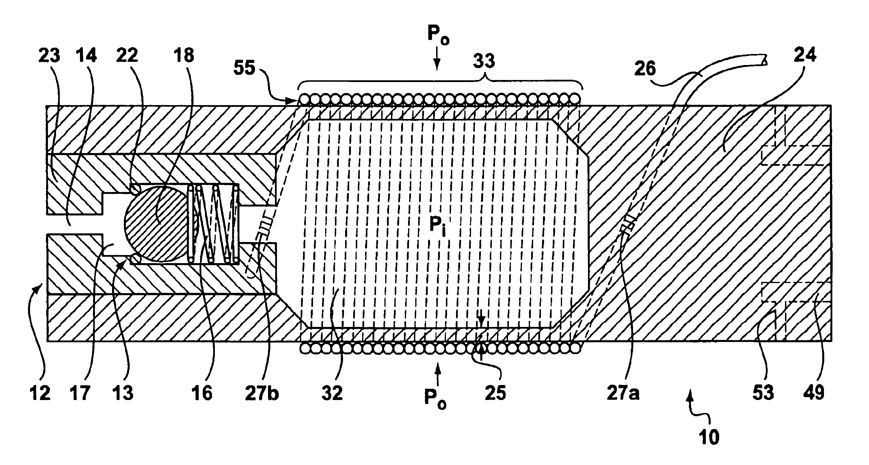
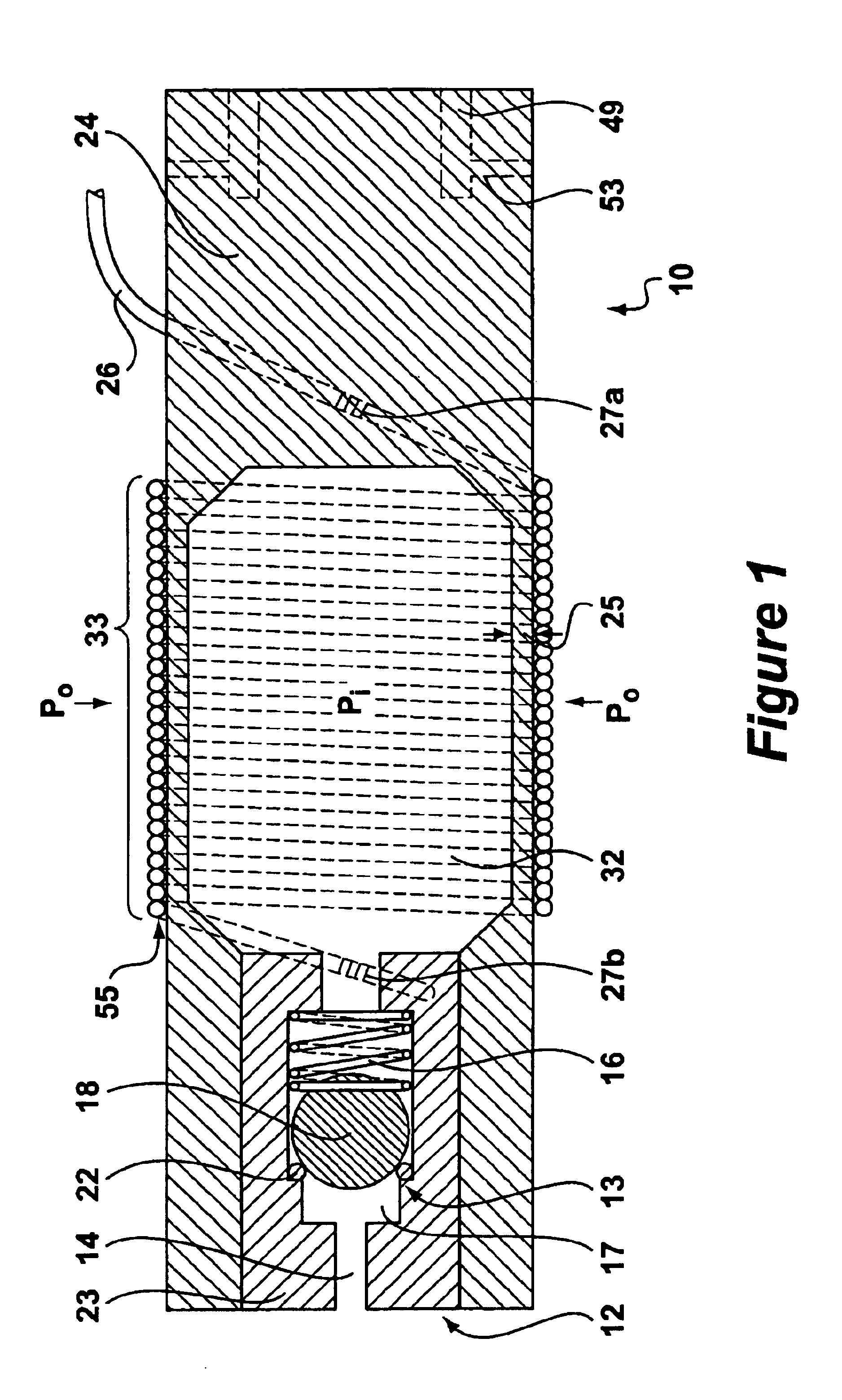
[0016]FIG. 1 depicts an embodiment of a pressure compensated hydrophone 10. The hydrophone 10 includes a preferably flattened oblique mandrel 24 (shown best in FIG. 4) that contains a ...


PUM


Abstract

A pressure compensated hydrophone for measuring dynamic pressures is disclosed. The hydrophone includes a compliant hollow mandrel with a single optical fiber coiled around at least a portion of the mandrel. The mandrel further includes at least one pressure relief valve for compensating for changes in hydrostatic pressure. The pressure relief valve includes a micro-hole, which allows hydrostatic pressures or low frequency pressure events to couple into the interior of the mandrel to provide compensation against such pressure. Higher frequencies pressure events of interest do not couple through the micro-hole and therefore only act only on the exterior of the mandrel, allowing for their detection. Because (quasi) hydrostatic events are compensated for, the mandrel may be made particularly compliant, rendering the singular fiber optic coil particularly sensitive to the detection of the higher frequency signals of interest.

Description

FIELD OF THE INVENTION[0001]This invention relates generally to hydrophones, and more particularly to a pressure compensated fiber optic hydrophone.BACKGROUND OF THE INVENTION[0002]Fiber optic hydrophones are well known in the art for measuring seismic and acoustic disturbances. Generally hydrophones are towed behind a ship to measure these disturbances. However, with the increasing development of subsea or land-based oil / well systems, a hydrophone that could be deployed down a well at extreme depths and that could withstand the extremely corrosive downhole environment would provide significant benefits. Such a hydrophone would improve the ability to explore the land surrounding a well site by seismology or to detect other acoustics downhole that could inform the well operator about various aspect of the well's production.[0003]While hydrostatic pressure has a measurable effect on a hydrophone, especially when the hydrophone is deployed at extreme depths, small dynamic pressures, su...

Claims


Application Information

Patent Timeline
Patent Type & Authority Patents(United States)
IPC IPC(8): H04R1/44
CPCH04R1/44G01V1/18
Inventor WOO, DANIEL MING KWONG
Owner WEATHERFORD TECH HLDG LLC
Why Eureka
Try Eureka