Method and apparatus for defect detection in optical disc drives

Active Publication Date: 2005-04-19
MEDIATEK INC
View PDF5 Cites 24 Cited by
  • Summary
  • Abstract
  • Description
  • Claims
  • Application Information

AI Technical Summary

Benefits of technology

[0013]It is an advantage of the invention that an accurate defect detection signal, regardless of the length of the disc defect, can be generated, improving the art of disc defect management.
[0014]These and other objectives of the invention will no doubt become obvious to those of ordinary skill in the art after reading the following detailed description of the preferred embodiment, which is illustrated in the various figures and drawings.

Problems solved by technology

Now, the difference between the SBAD and the SBAD_LPF is again less than the threshold, resulting in a defect signal no longer being generated.
However, the above defect detection method fails and generates inaccurate defect signals during a long defect as shown in FIG.
Additionally, an erroneous defect signal is generated from point T3 to point T4 during which the SBAD_LPF cannot return to the normal SBAD level rapidly enough and the difference between SBAD and SBAD_LPF is overly large, again triggering the defect signal.
The prior art generated defect signal can provide false information about the length of the defect, which may cause failure in disc defect management.

Method used


Image

  • Method and apparatus for defect detection in optical disc drives
  • Method and apparatus for defect detection in optical disc drives
  • Method and apparatus for defect detection in optical disc drives

Examples


Embodiment Construction

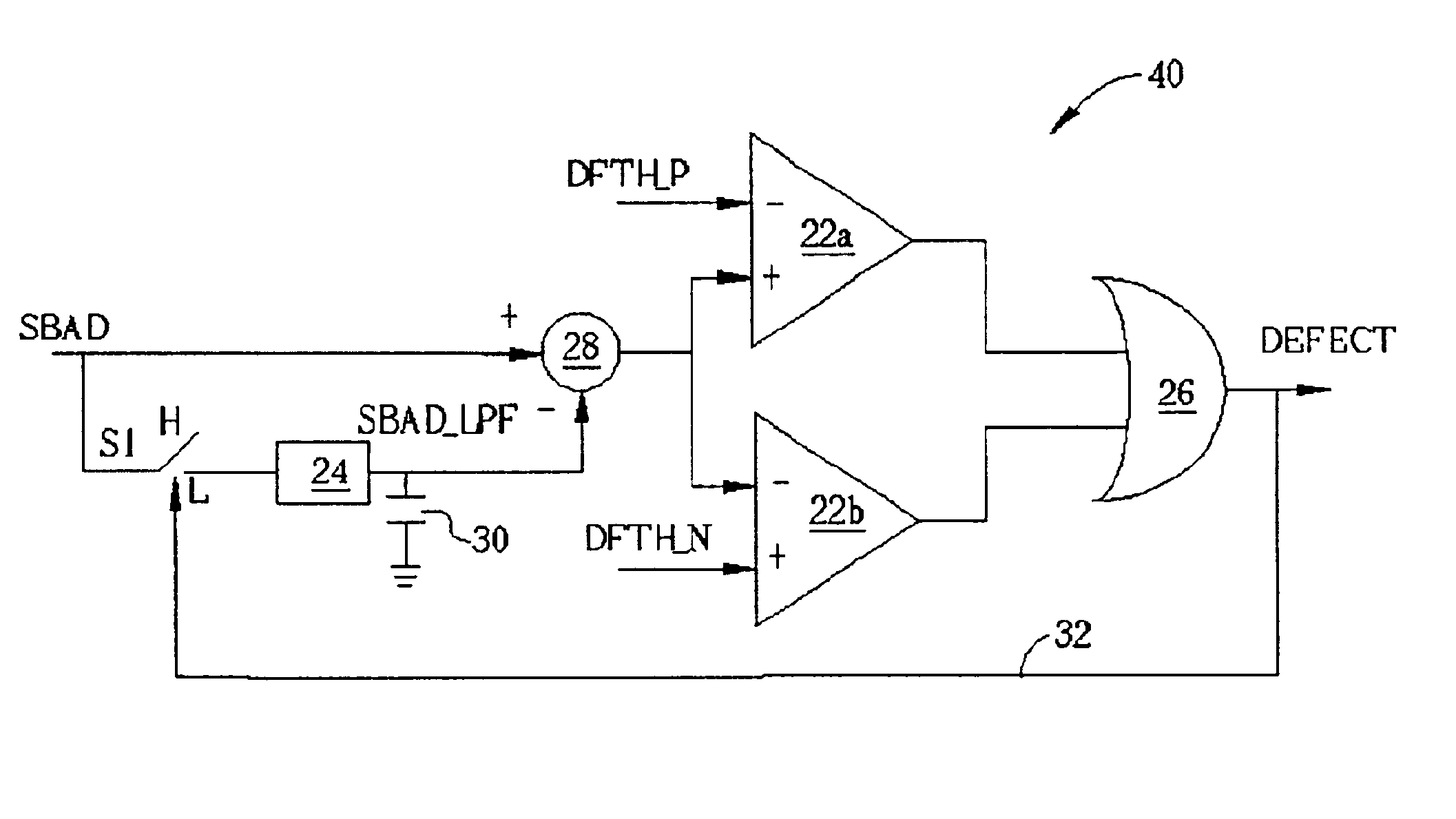
[0020]A present invention defect detection circuit 40 is shown in FIG. 5. The defect detection circuit 40 comprises the OR operator 26, the first comparator 22a, the second comparator 22b, the subtractor 28, and the low-pass filter 24.

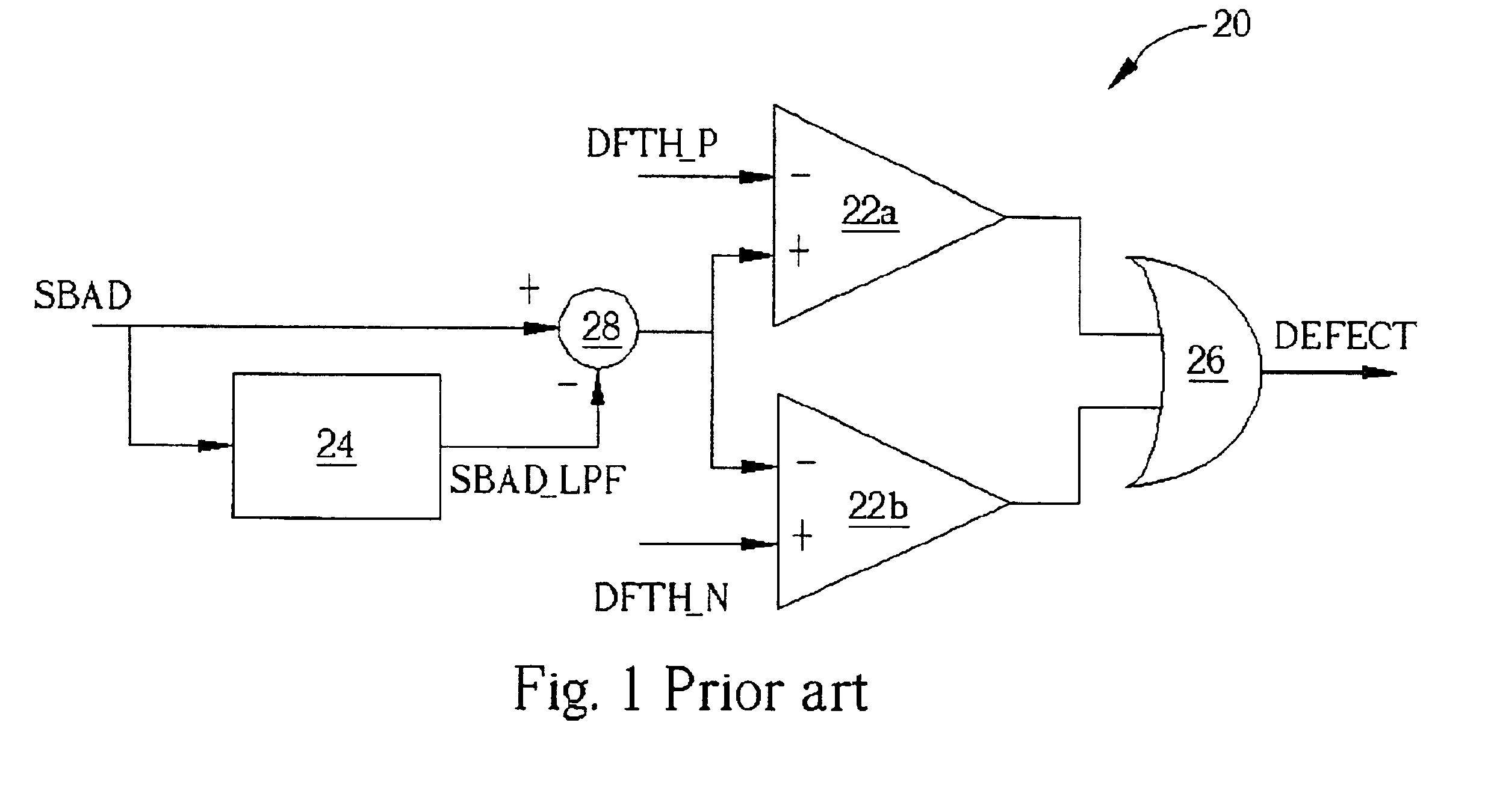
[0021]When no defect signal is generated, the defect detection circuit 40 operates similarly to the prior art. The sum of the sub-beams reflected by the disc (SBAD) is sent to the subtractor 28 via two paths, one being a direct path, the second being routed through the low-pass filter 24 where the SBAD is converted into a low-frequency signal (C). The subtractor 28 subtracts the SBAD_LPF from the SBAD and provides a difference signal to each of the comparators 22a, and 22b. The comparator 22a compares the difference signal with a first predetermined value (DFTH_P) and outputs the result to one input of the OR operator 26. The comparator 22b compares the difference signal with a second predetermined value (DFTH_N) and outputs the result to another input...


PUM


Abstract

A defect detection method is used to generate a disc defect signal while recording or reproducing information recorded onto an optical disc. The method compares the difference between a reflected light intensity signal (SBAD) and a low-pass filtered SBAD with a predetermined level. A defect signal is generated during a period when the difference exceeds a predetermined value. The defect signal opens a switch to hold the low-passed signal of the SBAD and disconnects the low-pass filter from the SBAD at the moment a defect signal occurs. The held value of the low-passed signal effectively replaces the low-passed signal until the difference between the SBAD and held low-passed signal returns to within the predetermined limits, which re-closes the switch re-connecting the low-pass filter to the SBAD.

Description

BACKGROUND OF INVENTION[0001]1. Field of the Invention[0002]The present invention relates to disc defect detection in data reproduction systems. More specifically, a method and an apparatus for accurately generating disc defect signals during data recording and / or data reproduction in an optical disc system is disclosed.[0003]2. Description of the Prior Art[0004]In data reproduction systems, such as a CD-RW drive and a DVD-RW drive, it is important to know which areas of a disc are unusable due to defects. In an information recording system that supports defect management, a defect circuit must be able to generate accurate defect signals for the correct duration of the defect during data recording and / or data reproduction.[0005]It is well known that an area of a disc containing a defect reflects the light differently than other areas of the same disc. A conventional defect detection system uses this variation in a reflected light intensity signal to determine the presence or absence...

Claims


Application Information

Patent Timeline
IPC IPC(8): G11B7/00G01N21/88G01N21/95G11B7/0037G11B20/18
CPCG11B20/18G11B7/00375G01N21/9506
Inventor CHEN, CHIH-YUAN
Owner MEDIATEK INC
Why Eureka
Try Eureka