
Tomosynthesis X-ray mammogram system and method with automatic drive system

Inactive Publication Date: 2005-04-19
GENERAL ELECTRIC CO
View PDF41 Cites 151 Cited by
  • Summary
  • Abstract
  • Description
  • Claims
  • Application Information

AI Technical Summary

Problems solved by technology

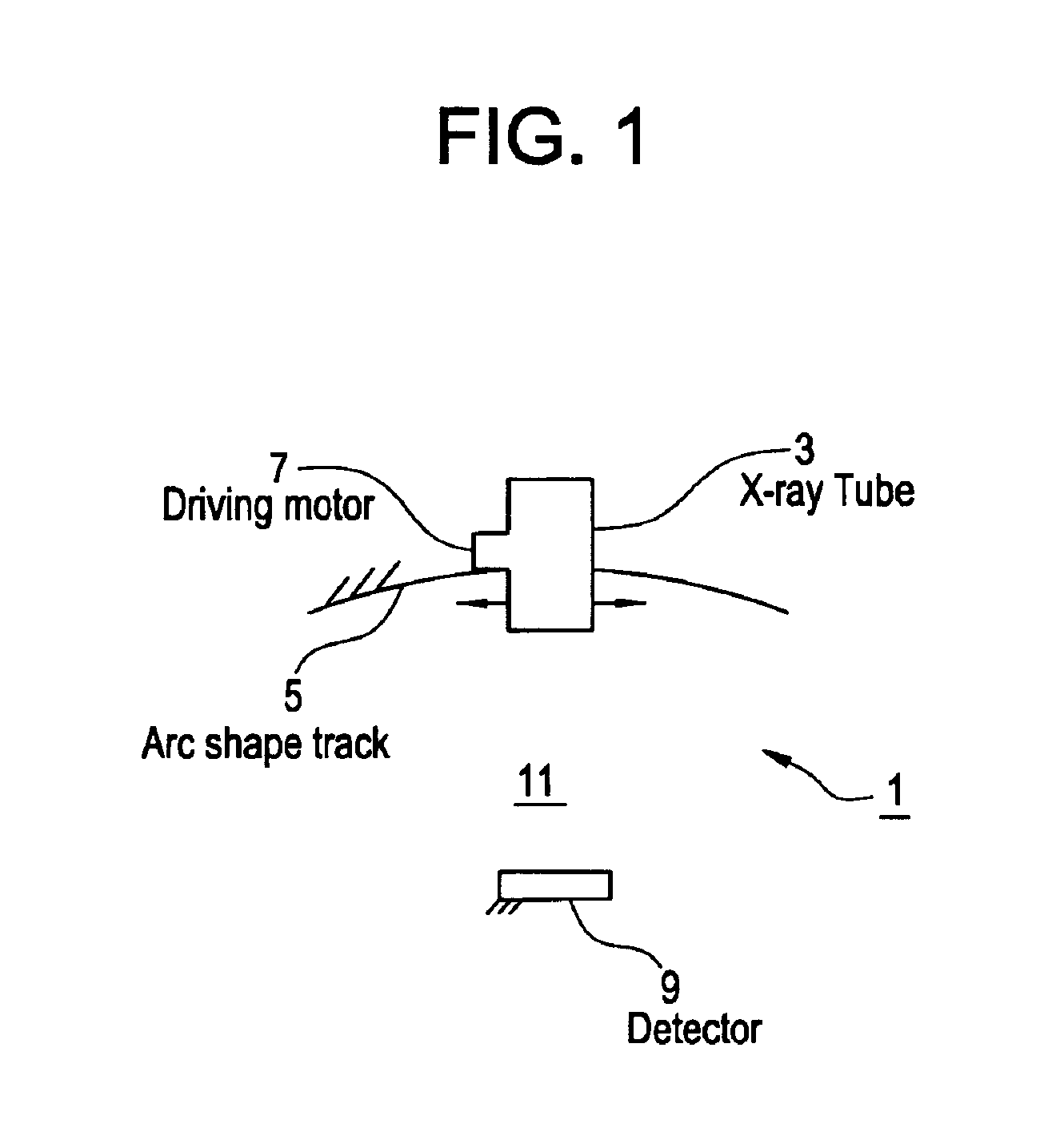
However, such a system produces a two dimensional image of the patient's breast, which provides insufficient information about the presence of tumors and calcification and often leads to false positive readings.
However, this tomosynthesis system suffers from several disadvantages.
First, the X-ray source is subject to a high amount of vibration because it is mounted to the free, upper end of a rotating arm, while the arm is supported only at the pivot point at its lower end.
Second, this system requires a high amount of driving power to move the X-ray source.

Method used


Image

  • Tomosynthesis X-ray mammogram system and method with automatic drive system
  • Tomosynthesis X-ray mammogram system and method with automatic drive system
  • Tomosynthesis X-ray mammogram system and method with automatic drive system

Examples


second embodiment

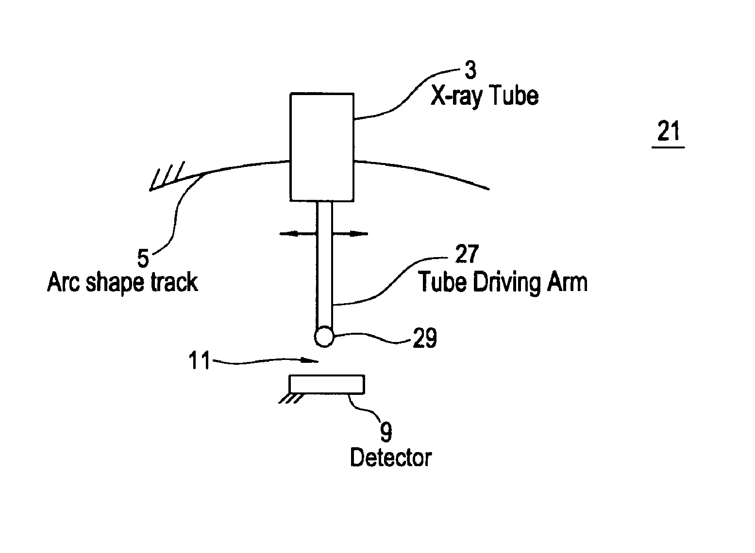
[0030]The system 31 of the third preferred embodiment is schematically illustrated in FIG. 4. In the third preferred embodiment, the X-ray source is supported by a rotational arm, which moves along an arc shaped track, rather than being supported by the track as in the first and Thus, the first support for the X-ray source 3 comprises a first arm 37. The arm 37 may have any desired shape, such as a tube or plate shape. The X-ray source 3 is mounted to an upper or first portion of the first arm 37. A lower or second portion of the first arm distal from the first portion is mounted to the arc shaped track 35.

[0031]The mechanical driving mechanism in this embodiment comprises a motor 7. The motor 7 is adapted to move the lower portion of the first arm 37 along the arc shaped track 35 to move the X-ray source 3 in the arc shaped path. The motor 7 may also be mounted onto the track if desired.

[0032]FIG. 5 illustrates a preferred configuration of the system 31 shown in schematic form in ...

fourth embodiment

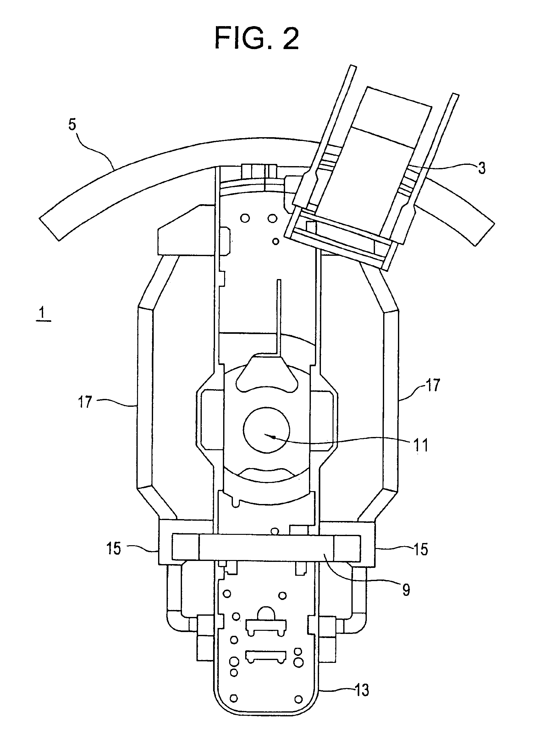
[0039]In a preferred embodiment of the fourth embodiment, a pivot point plate 44 is attached to the second arm 13, as shown in FIG. 7. The pivot point plate 44 is rotatably mounted to the linear motion track 45 by the side pin 43. The pivot plate 44 and track 45 optionally have holes 46 which reduce the weight of the plate 44 and track 45.

[0040]FIGS. 8 and 9 illustrate the method of operation of the system 41 of the fourth preferred embodiment. The X-ray source 3 is mounted to the first arm 47 such that it is positioned adjacent to the front side of the second arm 13. Thus, the X-ray source 3 moves in the arc shaped path in a plane parallel to the front side of the second arm. However, the first arm 47 itself is preferably positioned adjacent to the second or side of the second arm 13. A connector (not shown in FIGS. 8 and 9 for clarity) connects the upper portion of the X-ray source 3 to the upper portion of first arm 47, such that the X-ray source 3 and the first arm 47 may be mov...


PUM


Abstract

An imaging system includes an X-ray source adapted to move in an arc shaped path and a stationary electronic X-ray detector. The system also includes a track and a mechanical driving mechanism which is adapted to move the X-ray source in the arc shaped path. A tomosynthesis X-ray imaging method includes mechanically moving an X-ray source in a stepped motion on an arc shaped path around an object using a track and irradiating the object with an X-ray dose from the X-ray source located at a plurality of steps along the arc shaped path. The method also includes detecting the X-rays transmitted through the object with an electronic X-ray detector, and constructing a three dimensional image of the object from a signal output by the electronic X-ray detector.

Description

FEDERAL RESEARCH STATEMENT[0001]The U.S. Government may have certain rights in this invention pursuant to contract number DAMD 17-98-1-8309 awarded by the U.S. Army Medical Research and Materiel Command.BACKGROUND OF THE INVENTION[0002]The present invention relates generally to an imaging system, and more particularly to an X-ray mammogram tomosynthesis system.[0003]Conventional X-ray mammography imaging systems utilize an X-ray source mounted on a supporting frame. The frame is manually rotated by the system operator to a place the X-ray source into desired position adjacent to a patient's breast. The X-ray source emits a first shot of X-rays through the patient's breast and an image is captured on a first an X-ray sensitive film positioned on the opposite side of the patient's breast. The frame is then manually rotated into another position by the operator and a second X-ray sensitive film is exposed by a second shot of X-rays. This procedure can be repeated several times to gener...

Claims


Application Information

Patent Timeline
IPC IPC(8): A61B6/03A61B6/00
CPCA61B6/502A61B6/025A61B6/466A61B6/56
Inventor WANG, YUWIRTH, REINHOLD FRANZALEXANDER, JAMES PELLEGRINO
Owner GENERAL ELECTRIC CO
Learn More