Cast integral ring gear and differential case

Inactive Publication Date: 2005-04-26
MERITOR LIGHT VEHICLE TECH LLC
View PDF6 Cites 20 Cited by
  • Summary
  • Abstract
  • Description
  • Claims
  • Application Information

AI Technical Summary

Benefits of technology

[0005]The present invention provides an apparatus and method of forming a differential assembly which includes the steps of providing a ring gear, which is preferably produced by a precision forging process. The differential case is cast about a portion of the ring gear to secure the ring gear to the differential case and form the differential assembly. Preferab

Problems solved by technology

The ring gear is typically secured to differential case using numerous bolts, nuts and washers, which add costs and weight to the differential assembly.
However, utilizing forged steel for the entire differential assem

Method used


Image

  • Cast integral ring gear and differential case
  • Cast integral ring gear and differential case

Examples


Embodiment Construction

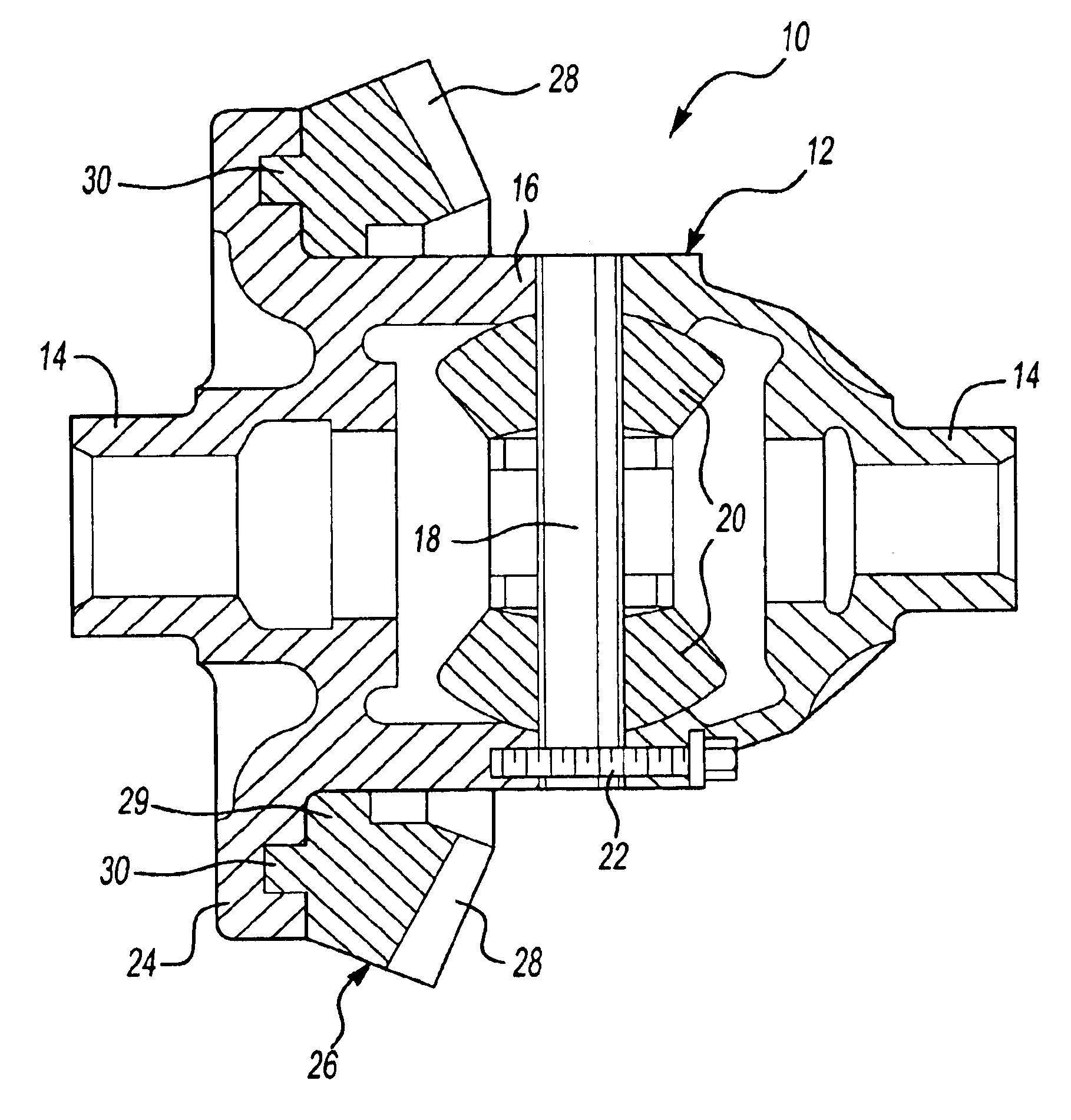
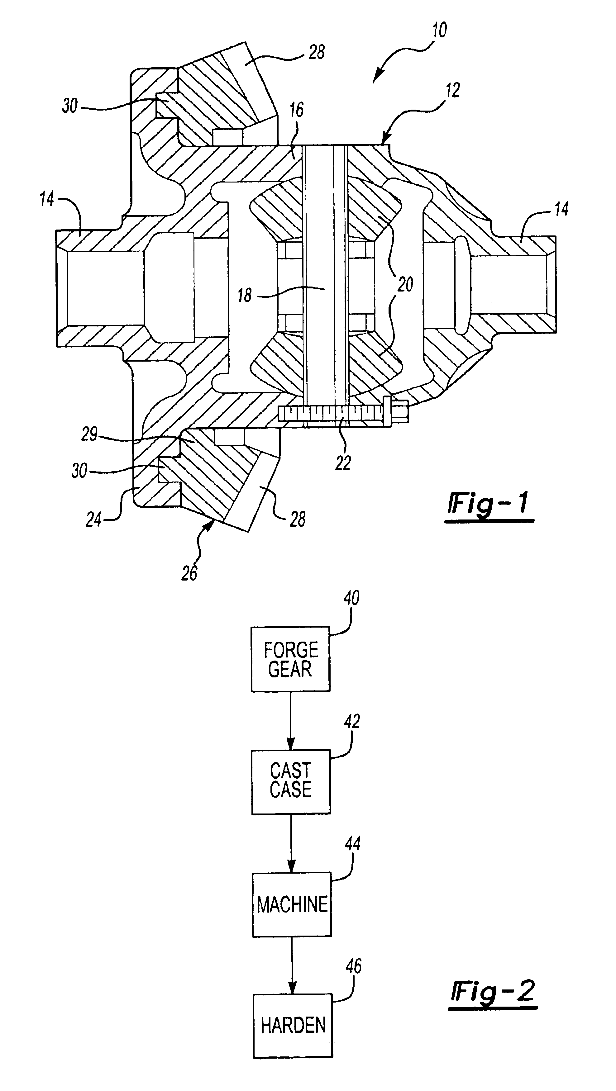
[0010]A differential assembly 10 is shown in FIG. 1. The differential assembly 10 includes a differential case 12, which is preferably constructed from ductile iron. The differential case 12 includes opposing ends 14 that receive and support opposing axle shafts, which are not shown in the Figure. While the differential assembly 10 is discussed with reference to vehicle axles, it is to be understood that the present invention may be utilized for other applications. The differential case 12 includes a central portion 16 having a spider 18 supporting differential pinions 20, which engage side gears on the axle shafts. The differential case shown is a two-piece configuration with fasteners 22 securing the pieces together. However, it is to be understood that the invention may be used for any differential assembly configuration. The spider 18, pinions 20, and fasteners 22 are installed after the casting and machining processes discussed below.

[0011]The differential case 12 further inclu...


PUM

PropertyMeasurementUnit
Ductilityaaaaaaaaaa

Abstract

An apparatus and method of forming a differential assembly is provided that includes the steps of providing a ring gear, which is preferably produced by a precision forging process. The differential case is cast about a portion of the ring gear to secure the ring gear to the differential case and form the differential assembly. Preferably, the ring gear includes projections that are embedded in the differential case during the casting process to enhance the connection between the ring gear and the differential case. In this manner, the ring gear may be constructed from a forged steel and the differential case may be constructed from ductile iron while eliminating the fasteners of the prior art.

Description

BACKGROUND OF THE INVENTION[0001]This invention relates to a differential assembly for use in an axle, and more particularly, the invention relates to a ring gear and differential case used in a differential assembly.[0002]Differential assemblies are commonly used in axles and other rotational transmission devices to provide relative rotation between shafts arranged along a common axis. The differential assembly typically receives rotational input from a drive shaft transverse to the common axis. The rotational input is transmitted through the differential assembly by a ring which is secured to a differential case. The differential case supports the ends of the shafts and the gears necessary to permit relative rotation of the shafts.[0003]The ring gear is typically secured to differential case using numerous bolts, nuts and washers, which add costs and weight to the differential assembly. The ring gear and differential case are manufactured separately and secured to one another, whi...

Claims


Application Information

Patent Timeline
IPC IPC(8): B21K1/28B21K1/30F16H48/06F16H48/08F16H48/38F16H48/40F16H57/02
CPCB21K1/30F16H48/06F16H48/08F16H48/40Y10T29/49231F16H2048/385Y10T29/49464Y10T74/2186Y10T29/49465F16H2048/382
Inventor BELL, DALE K.
Owner MERITOR LIGHT VEHICLE TECH LLC
Why Eureka
Try Eureka