Al technical title is built by PatSnap Al team. It summarizes the technical point description of the patent document.
a transducer and magnetic circuit technology, applied in the field of magnetic circuit arrangement, can solve the problems of sensor signals having a very poor signal-to-noise ratio, large inaccuracy, temperature-induced shifts, etc., and achieve the effect of preventing the magnetic field
Inactive Publication Date: 2005-04-26
ENDRESS HAUSER FLOWTEC AG
View PDF13 Cites 110 Cited by
Summary
Abstract
Description
Claims
Application Information
AI Technical Summary
This helps you quickly interpret patents by identifying the three key elements:
Problems solved by technology
Method used
Benefits of technology
Problems solved by technology
It turned out, however, that although the above-described mechanical stresses can thus be virtually completely eliminated, the accuracy of such a magnetic circuit arrangement may be seriously affected by, particularly temperature-induced, shifts between the holding structure and the double flow tube configuration as occur, for example, in applications for fluids with widely varying temperatures.
While in the magnetic circuit arrangement according to U.S. Pat. No. 6,138,517, mainly a very great temperature difference, and thus a very great expansion difference, may occur between holding structure and double flow tube configuration, in the magnetic circuit arrangements described in U.S. Pat. No. 5,349,872, whose magnetic fields, particularly in the areas of the armatures, are highly inhomogeneous, even slight disturbances may result in considerable inaccuracy.
As a result, e.g., if the arrangement is used as a vibration sensor, the sensor signals may have a very poor signal-to-noise ratio and / or exhibit very high harmonic distortion.
Furthermore, the magnetic field of a magnetic circuit arrangement as disclosed in U.S. Pat. No. 5,349,872 may act through a very large region, i.e., it may also penetrate adjacent components of the transducer and particularly other such magnetic circuit arrangements and / or the flow tubes with the fluid passing therethrough, thus inducing interference voltages, for example.
Further disadvantages of such a magnetic circuit arrangement are discussed in detail in U.S. Pat. No. 6,138,517, for example.
Method used
Image
Click on the blue label to locate the original text in one second.
Reading with bidirectional positioning of images and text.
Examples
Embodiment Construction
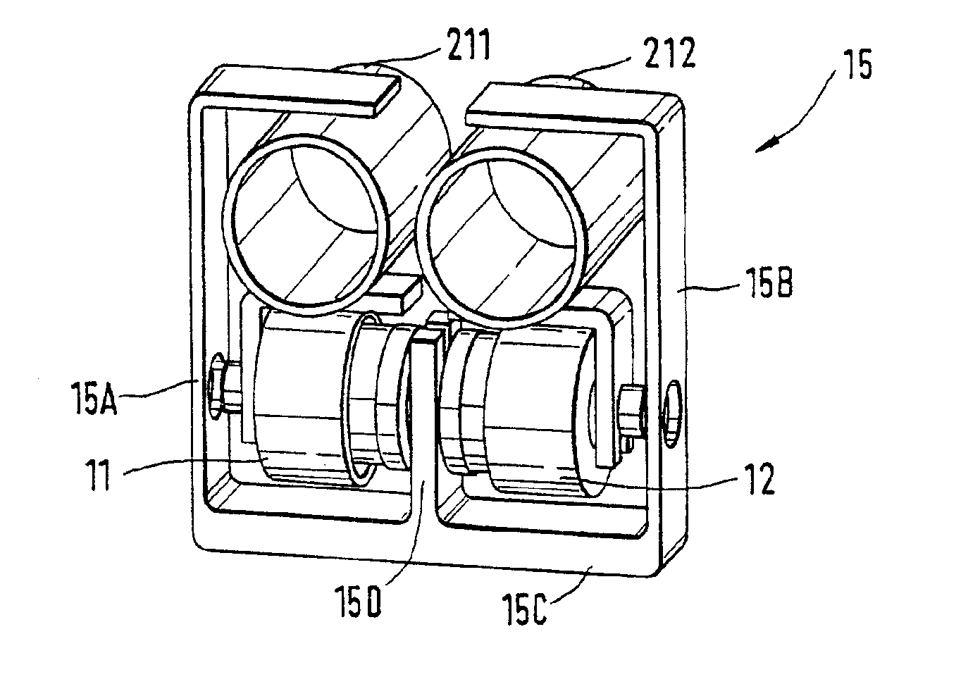
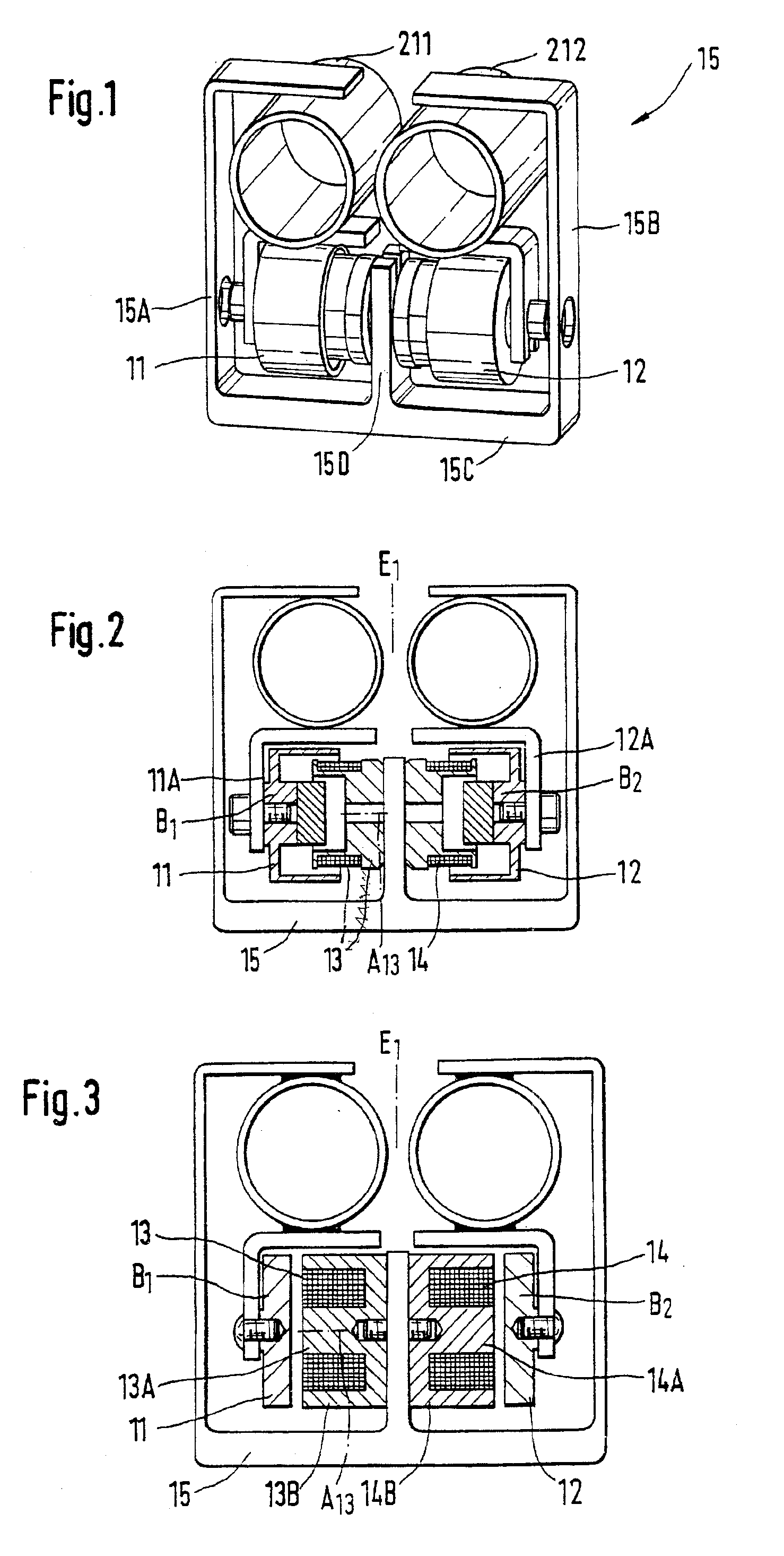
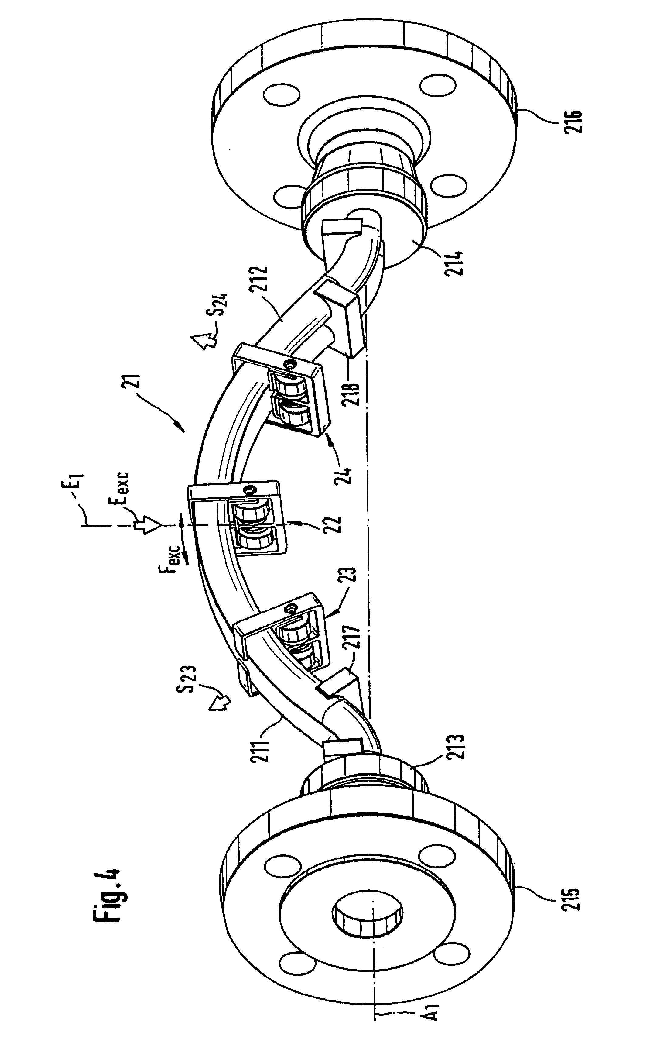
[0048]FIGS. 1 to 3 show embodiments of a magnetic circuit arrangement for converting electrical energy into mechanical energy and / or, based on the law of electromagnetic induction, for converting mechanical into electrical energy. The magnetic circuit arrangement is particularly suited for use in a Coriolis mass flowmeter or a Coriolis mass flowmeter-densimeter. A corresponding embodiment of a vibratory transducer, wirich responds to the mass flow rate m of a fluid flowing in a pipe (not shown), is shown in FIG. 4. As is well known, such a mass flow sensor, if used as a physical-to-electrical transducer in a Coriolis mass flowmeter, serves to produce and detect Coriolis forces in the fluid passing therethrough and to convert these forces into useful input signals for subsequent evaluation electronics.
[0049]To conduct the fluid to be measured, the transducer comprises a double flow tube configuration 21 with a first flow tube 211 and a second flow tube 212, which is preferably identi...
PUM
Abstract
The magnetic circuit arrangement, which is preferably used in a fluid-measuring transducer, comprises at least one coil which is traversed in operation by a current. It further comprises two armatures that are fixed to two flow tubes vibrating in phase opposition. The coil is float-mounted by means of a holder to a double flow tube configuration formed by the flow tubes. The armatures are shaped and aligned relative to each other in such a manner that magnetic fields produced by means of the magnetic circuit arrangement are essentially concentrated within the magnetic circuit arrangement, whereby the latter is also largely insensitive to extraneous magnetic fields. The magnetic circuit arrangement is marked by a long service life and, particularly if the transducer is used for fluids with high and / or varying temperatures, by constantly high accuracy in operation.
Description
[0001]This application is based on Provisional Application, filed Apr. 27, 2001, as application No. 60 / 286,546.FIELD OF THE INVENTION[0002]This invention relates to a magnetic circuit arrangement for use in a vibratory transducer and particularly in a Coriolis mass flow sensor.BACKGROUND OF THE INVENTION[0003]To determine the mass flow rate a fluid flowing in a pipe and particularly of a liquid, use is frequently made of Coriolis mass flowmeters, which, as is well known, induce Coriolis forces in the fluid and derive therefrom a measurement signal representative of mass flow rate by means of a vibratory transducer and control and evaluation electronics connected thereto.[0004]Such Coriolis mass flowmeters have been known and in industrial use for a long time. For example, U.S. Pat. Nos. 4,756,198, 4,801,897, 5,048,350, 5,301,557, 5,349,872, 5,394,758, 5,796,011, and 6,138,517 as well as EP-A 803 713 disclose Coriolis mass flowmeters incorporating a transducer which comprises:[0005]a...
Claims
Application Information
Patent Timeline
Application Date:The date an application was filed.
Publication Date:The date a patent or application was officially published.
First Publication Date:The earliest publication date of a patent with the same application number.
Issue Date:Publication date of the patent grant document.
PCT Entry Date:The Entry date of PCT National Phase.
Estimated Expiry Date:The statutory expiry date of a patent right according to the Patent Law, and it is the longest term of protection that the patent right can achieve without the termination of the patent right due to other reasons(Term extension factor has been taken into account ).
Invalid Date:Actual expiry date is based on effective date or publication date of legal transaction data of invalid patent.