Power tool for fastening objects

Inactive Publication Date: 2005-04-26
HYTORC DIV UNEX CORP
View PDF27 Cites 62 Cited by
  • Summary
  • Abstract
  • Description
  • Claims
  • Application Information

AI Technical Summary

Benefits of technology

[0007]The drag friction created by the nut on the bolt can be quite high. It is the object of the present invention to use a power tool's reaction force in a way that allows the bolt to move in an axial direction when the nut is turned. Therefore, to stop the bolt from turning with or in the thir

Problems solved by technology

Secondly, the customer uses

Method used


Image

  • Power tool for fastening objects
  • Power tool for fastening objects
  • Power tool for fastening objects

Examples


Embodiment Construction

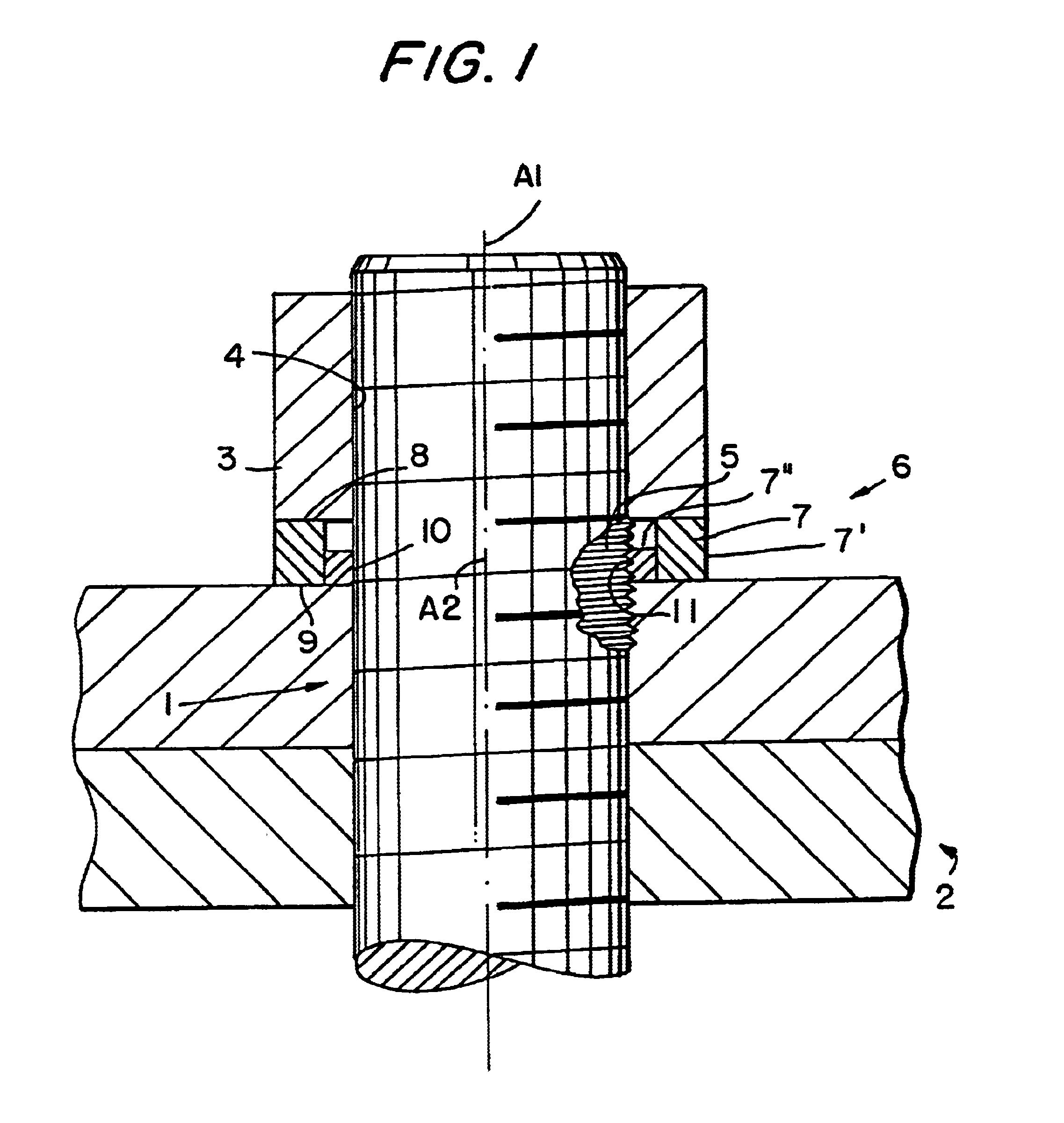
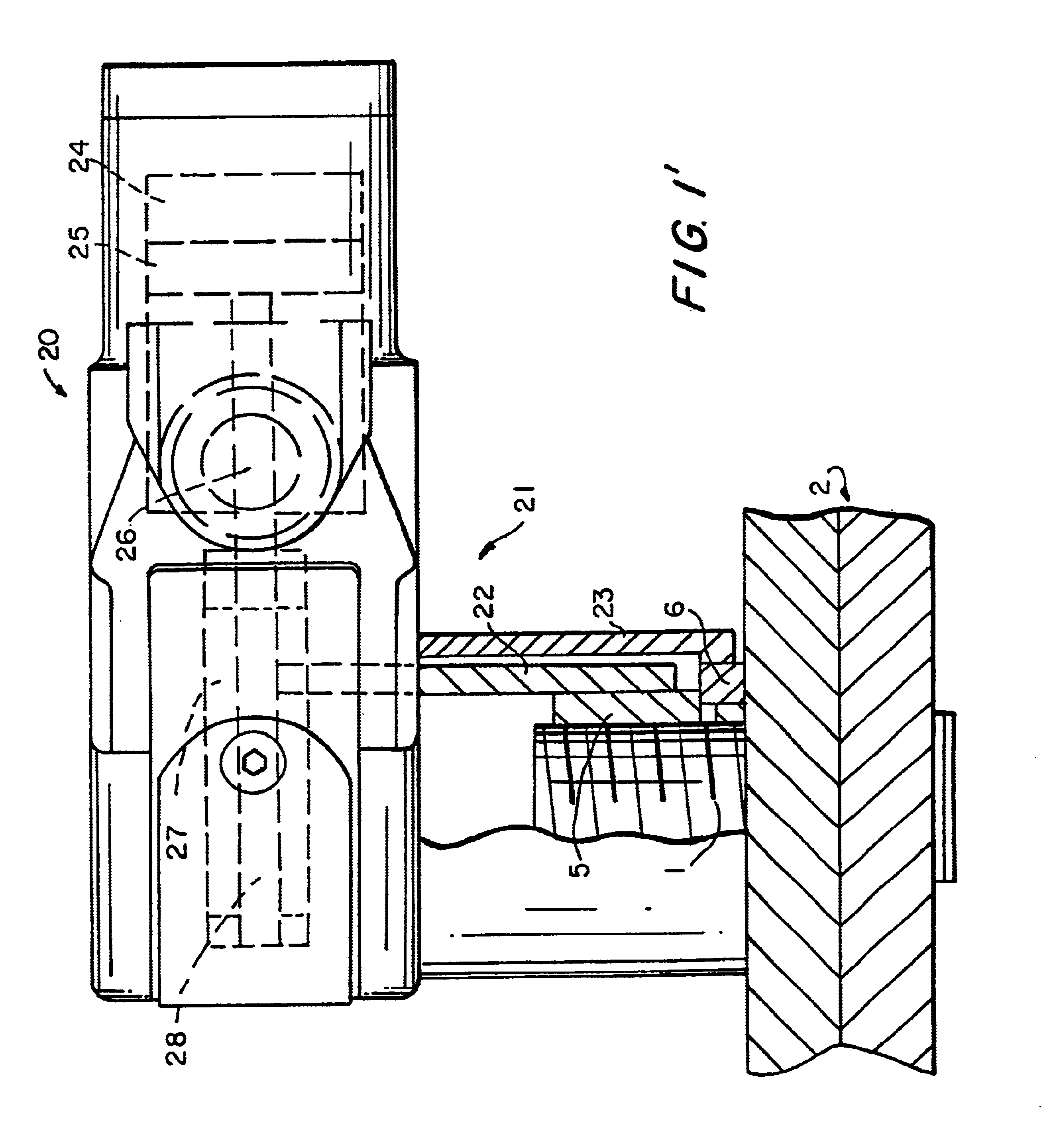
[0024]FIG. 1′ shows a power tool in accordance with the present invention. The powertool can be an electrically driven, pneumatically driven, hydraulically driven, or manually driven power tool. It has a power tool part with a housing identified as a whole with reference numeral 20, and a power drive in the housing and identified with reference numeral 21. The power tool part further has a rotatable driving element 22 which is to be connected to a nut of a fastener and turn the nut to overcome a thread friction with a bolt and a facial friction with a washer to turn the nut, and a non-rotatable element 23 connectable to a washer to absorb the reaction force due to the facial friction of the washer with the nut, its facial friction with one side of two parts to be fastened with one another, and its turning friction with the bolt, so that the washer and the bolt do not turn but absorb the reaction force of the power tool.

[0025]The power drive of the power tool part can include a cylin...


PUM


Abstract

A power tool for fastening objects has a housing with a non-rotatable element, a power drive in the housing and provided with a rotatable driving element, and a fastener part including a bolt having a thread and an axis and introducable into parts forming an object, a nut screwable on the bolt and cooperating with the rotatable driving element, and a washer to be applied between the nut and an object and cooperating with the non-rotatable element, the washer having an axis and being provided with a first bearing face surface located at one axial side and adapted to cooperate with the nut, a second bearing face surface located at an opposite axial side and adapted to cooperate with the object, and at least one third turning resistant surface adapted to cooperate with the thread of the bolt, so that when driving element turns the nut with a given active force in one direction and the washer is held stationarily applied by the non-rotatable element of the housing, the nut turns to tighten or loosen the bolt, and the washer remains rotation stationary while the bolt elongates or relaxes in an axial direction.

Description

CROSS-REFERENCE TO A RELATED APPLICATION[0001]This application is a continuation-in-part of application Ser. No. 10 / 010,377 filed on Dec. 6, 2001 now U.S. Pat. No. 6,609,868.BACKGROUND OF THE INVENTION[0002]The present invention relates to a tool for fastening objects.[0003]It is known to fasten objects with one another with power tools which use fasteners having a multi-part replacement nut, for example including an inner sleeve, an outer sleeve, and a washer. Such a replacement nut is disclosed for example in our U.S. Pat. No. 5,341,560. Another replacement nut is disclosed in our U.S. Pat. No. 6,254,323 in which a bolt has a spline underneath its upper thread, to which a washer is non-rotatably connected, and the bolt also has engaging means for applying a reaction force, while an active force of the same tool turns the nut on the bolt thread and the washer face. In the fastener disclosed in both above mentioned patents, the common features are the use of the action and reaction ...

Claims


Application Information

Patent Timeline
IPC IPC(8): B25B23/02B25B23/10F16B43/00F16B5/02
CPCB25B23/10F16B43/00F16B5/02Y10S411/917
Inventor JUNKERS, JOHN K.
Owner HYTORC DIV UNEX CORP
Why Eureka
Try Eureka