Variable valve timing controller

a timing controller and variable valve technology, applied in the direction of valve details, valve arrangements, valve drives, etc., can solve the problem of unnecessarily varying the rotational phase of the driven shaft relative to the driving sha

Inactive Publication Date: 2005-04-26
DENSO CORP +1
View PDF4 Cites 29 Cited by
  • Summary
  • Abstract
  • Description
  • Claims
  • Application Information

AI Technical Summary

Benefits of technology

[0006]The present invention is made in view of the above matters, and it is an object of the present invention to provide the VVT controller which restricts rotational-phase fluctuations of the driven shaft if the force is applied to the phase adjusting mechanism.

Problems solved by technology

When an engine torque is varied and some force are applied to the phase adjusting mechanism, the operation member may slide in the groove so that the rotational phase of the driven shaft unnecessarily varies relative to the driving shaft.

Method used


Image

  • Variable valve timing controller
  • Variable valve timing controller
  • Variable valve timing controller

Examples


first embodiment

(First Embodiment)

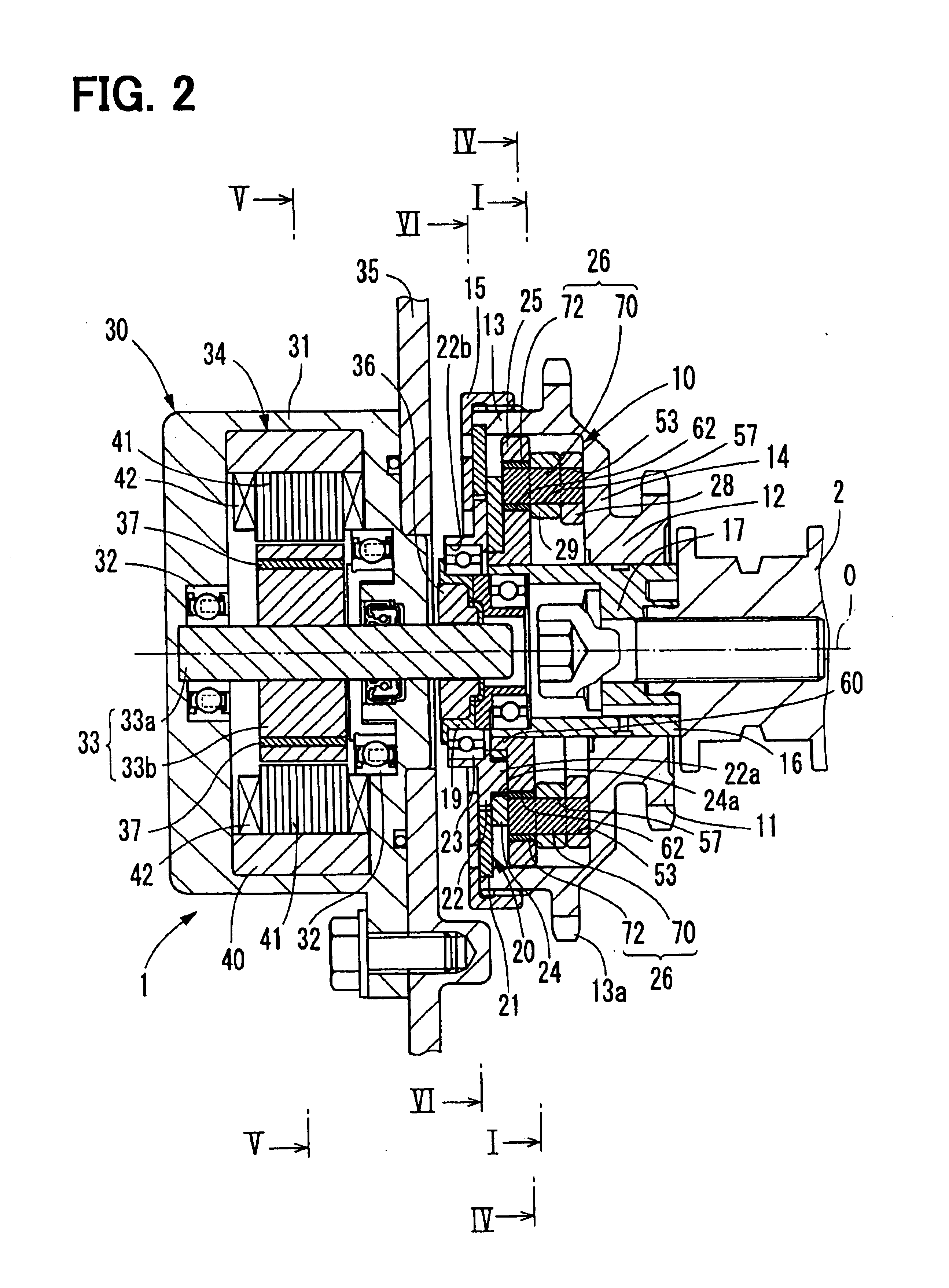
[0031]FIG. 2 shows a VVT controller according to the first embodiment of the present invention. The VVT controller 1 is disposed in a torque transfer system which transfers the torque of a crankshaft to a camshaft which opens and closes at least one of an intake valve or an exhaust valve. The crankshaft is a driving shaft and the camshaft is a driven shaft in this embodiment. The VVT controller 1 adjusts the valve timing of intake valve by varying the rotational phase of the camshaft 2 relative to the crankshaft.

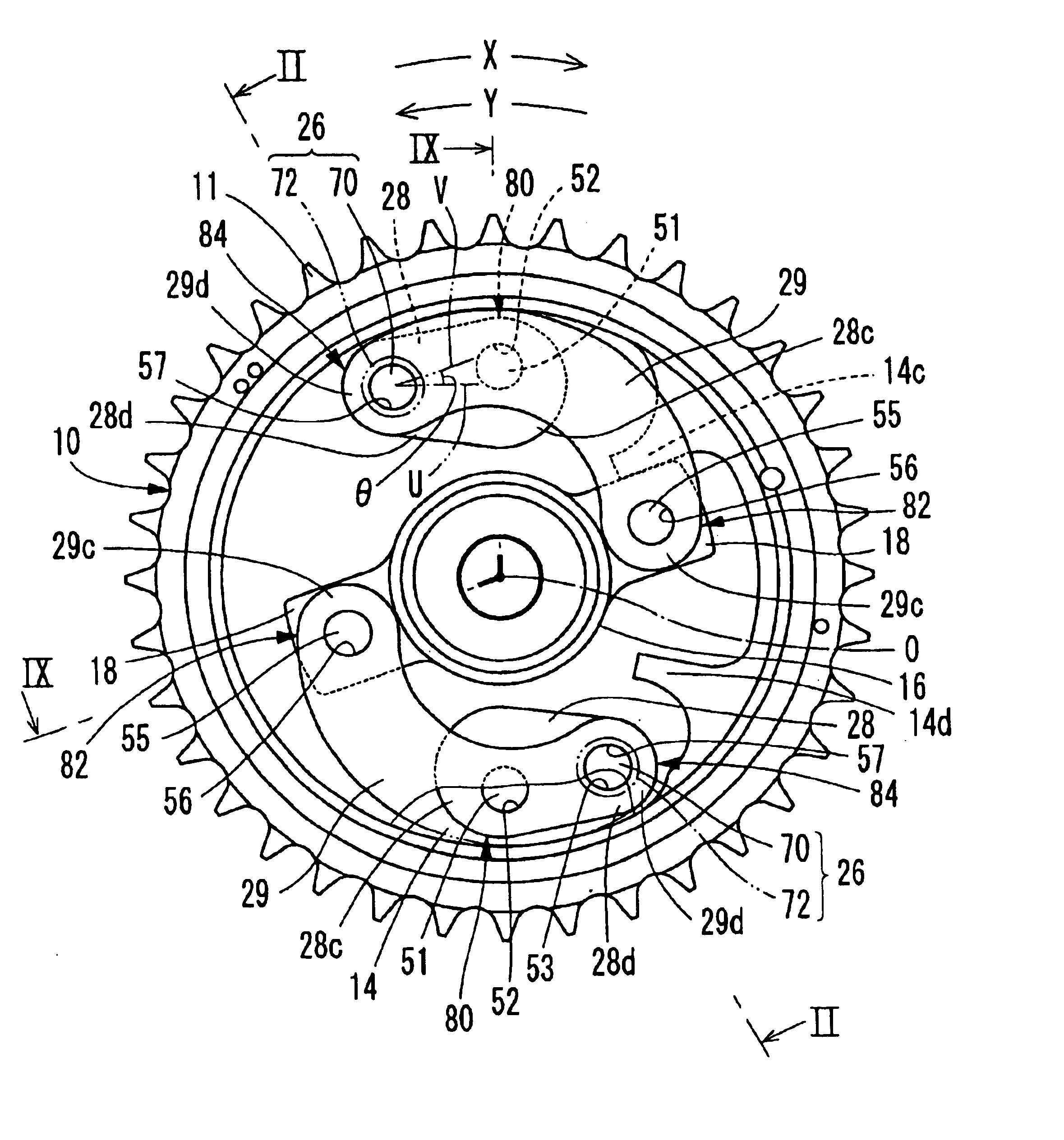
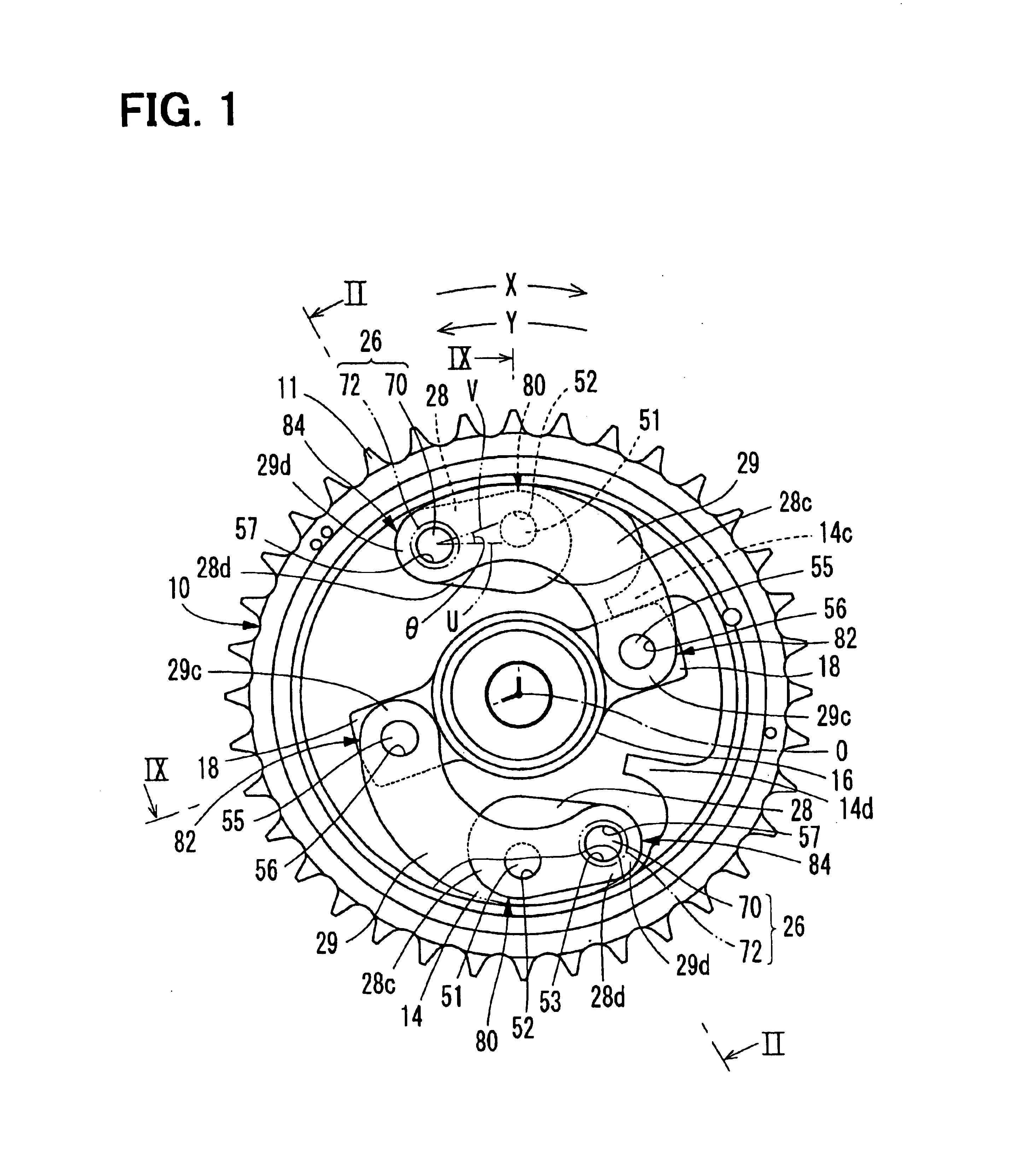
[0032]A phase adjusting mechanism 10 shown in FIGS. 1 and 2 has a sprocket 11, an output shaft 16, a first arm 28 and a second arm 29. The phase adjusting mechanism 10 varies a rotational phase of the camshaft 2 relative to a crankshaft (not shown). In FIGS. 1, 4, 7 and 8, hatching to show cross section are omitted.

[0033]The sprocket 11 has a supporting portion 12, an input portion 13 having a larger diameter than that of the supporting portion 12, and a li...

second embodiment

(Second Embodiment)

[0059]A VVT controller according to the second embodiment of the present invention is described in FIG. 12. The second embodiment is a modification of the first embodiment, and the substantially same parts and components as those in the first embodiment are indicated with the same reference numerals.

[0060]In the phase adjusting mechanism 100, the first arm 28 and the second arm 29 has the same length and the same angle θ as those in the first embodiment. The revolute pair 82, the revolute pair 80 and the revolute pair 84 are arranged in this order in the delay direction Y to reduce the size thereof.

[0061]The operation of the phase adjusting mechanism 100 is described herein after. When the distance between the movable member 26 and the center axis “O” increase, the first arm 28 moves the revolute pair 84 away from the center axis “O” according to the movement of the movable member 26, and the second arm 29 moves the revolute pair 82 in the advance direction X rela...

third embodiment

(Third Embodiment)

[0064]FIG. 13 shows a third embodiment of the present invention. The third embodiment is a modification of the first embodiment, and the substantially same parts and components as those in the first embodiment are indicated with the same reference numerals.

[0065]A phase adjusting mechanism 150 includes the first arm 28 and the second arm 29 having the same length as those of the first embodiment. The angle θ between the first arm 28 and the second arm 29 varies from 90° angle to 180° angle. The revolute pair 82, the revolute pair 84 and the revolute pair 80 are arranged in this order in the delay direction Y.

[0066]The operation of the phase adjusting mechanism 150 is described herein after. When the distance between the movable member 26 and the center axis “O” increases, the first arm 28 moves the revolute pair 84 away from the center axis “O” and the second arm 29 moves the revolute pair 82 in the delay direction Y relative to the revolute pair 80. Thereby, the o...


PUM


Abstract

The variable valve timing controller controls the valve timing of the intake valve. The variable valve timing controller has a phase adjusting mechanism which includes a first rotating member, a second rotating member, a first arm, and a second arm. The first rotating member rotates in synchronism with a driving shaft and the second rotating member rotates in synchronism with a driven shaft. The first arm is pivoted on the first rotating member and the second arm is pivoted on the second rotating member and the first arm. The phase adjusting mechanism varies the rotational phase of the driven shaft relative to the driving shaft with converting the a movement of the first arm and the second arm into the rotational movement of the first rotating member and the second rotating member.

Description

CROSS REFERENCE TO RELATED APPLICATION[0001]This application is based on Japanese Patent Application No. 2003-283016 filed on Jul. 30, 2003, the disclosure of which is incorporated herein by reference.FIELD OF THE INVENTION[0002]The present invention relates to a variable valve timing controller which changes opening and timing of intake valves and / or exhaust valves of an internal combustion engine according to operating condition of the engine. The opening and closing timing is referred to as valve timing, the variable valve timing controller is referred to as the VVT controller, and the internal combustion engine is referred to as an engine hereinafter.BACKGROUND OF THE INVENTION[0003]The VVT controller is disposed in a torque transfer system which transfers the torque of the driving shaft of the engine to the driven shaft which opens and closes at least one of an intake valve or an exhaust valve. The VVT controller adjusts the valve timing of the valves by varying a rotational ph...

Claims


Application Information

Patent Timeline
Patent Type & Authority Patents(United States)
IPC IPC(8): F01L1/344F01L1/352F01L1/34
CPCF01L1/352F01L1/344
Inventor TAKENAKA, AKIHIKOINOHARA, TAKAYUKI
Owner DENSO CORP
Why Eureka
Try Eureka