
Method of preventing preignition for an internal combustion engine

a technology of internal combustion engine and pre-ignition prevention, which is applied in the direction of electric control, ignition automatic control, machines/engines, etc., can solve the problems of improper heat range of spark plug electrodes, damage to cylinders, pistons, valves, etc., and achieve the effect of reducing the throttle opening

Inactive Publication Date: 2005-04-26
GM GLOBAL TECH OPERATIONS LLC
View PDF12 Cites 36 Cited by
  • Summary
  • Abstract
  • Description
  • Claims
  • Application Information

AI Technical Summary

Problems solved by technology

Autoignition may cause damage to the cylinders, pistons, and valves.
Causes of preignition include, but are not limited to, low coolant, coolant system deposits, combustion chamber deposits, improper sparkplug heat range, and spark plug electrode wear and failure.
Additionally, the use of low octane fuel, lower than the control capability of the knock control system within the engine management system, may cause preignition.
Poor fuel flow resulting in a lean air / fuel ratio may also lead to preignition.

Method used


Image

  • Method of preventing preignition for an internal combustion engine
  • Method of preventing preignition for an internal combustion engine
  • Method of preventing preignition for an internal combustion engine

Examples


Embodiment Construction

[0012]The following description of the preferred embodiment is merely exemplary in nature and is in no way intended to limit the invention, its application, or uses.

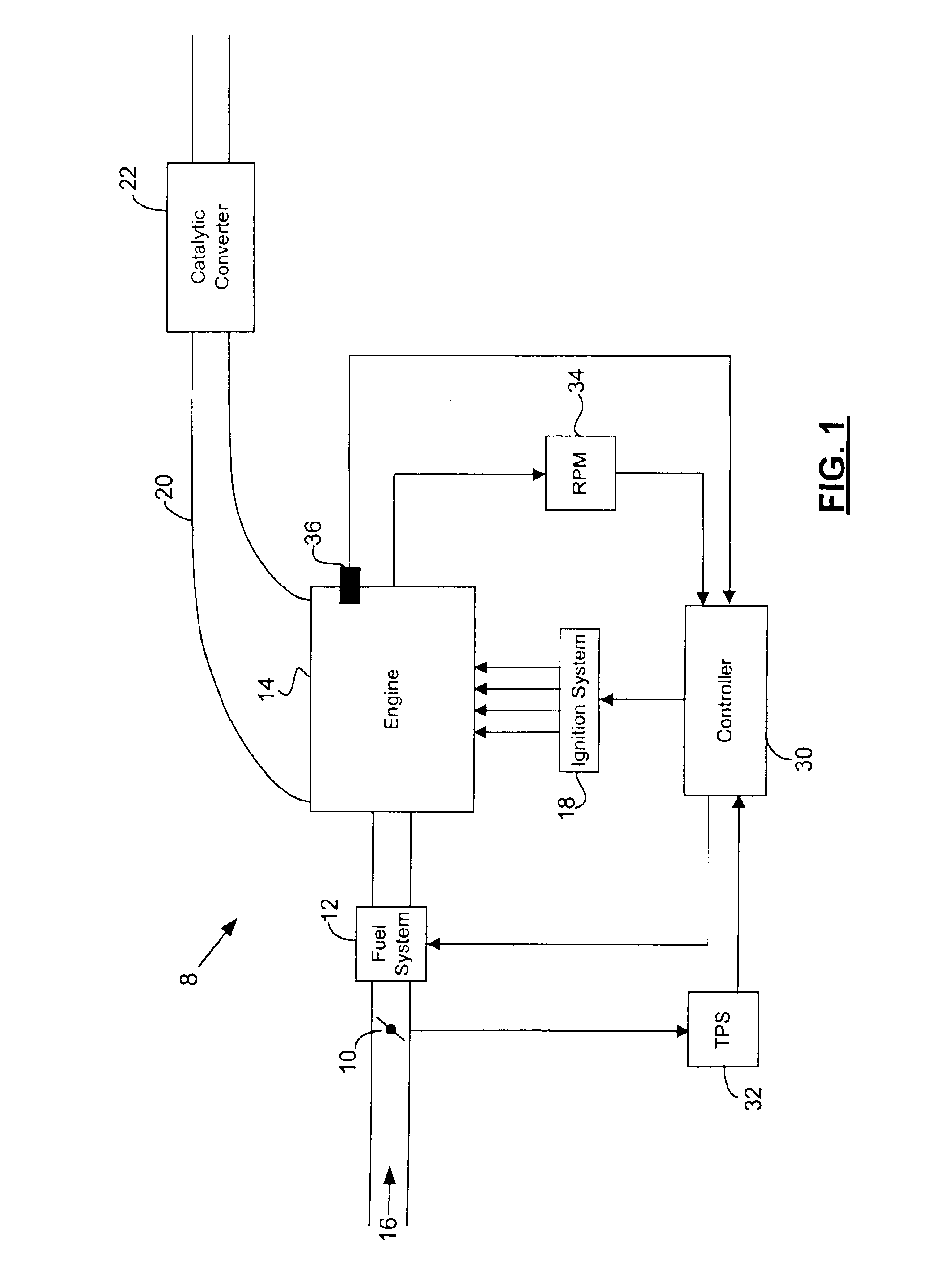
[0013]Referring to FIG. 1, an exemplary engine control system 8 is shown. A throttle 10 and a fuel system 12 determine the air and fuel delivered to an engine 14 through an intake 16. An ignition system 18 ignites the air / fuel mixture in the engine 14. Exhaust gas created by the ignition of the air / fuel mixture is expelled through an exhaust manifold 20. A catalytic converter 22 receives the exhaust gas and reduces the emissions levels of the exhaust gas.

[0014]A controller 30 communicates with various components of the engine control system 8, including but not limited to a throttle position sensor 32 (TPS), the fuel system 12, the ignition system 18, and an engine speed sensor 34 (RPM). The controller 30 receives a throttle position signal from the TPS 32 and uses the information to determine airflow into the engine 14....


PUM


Abstract

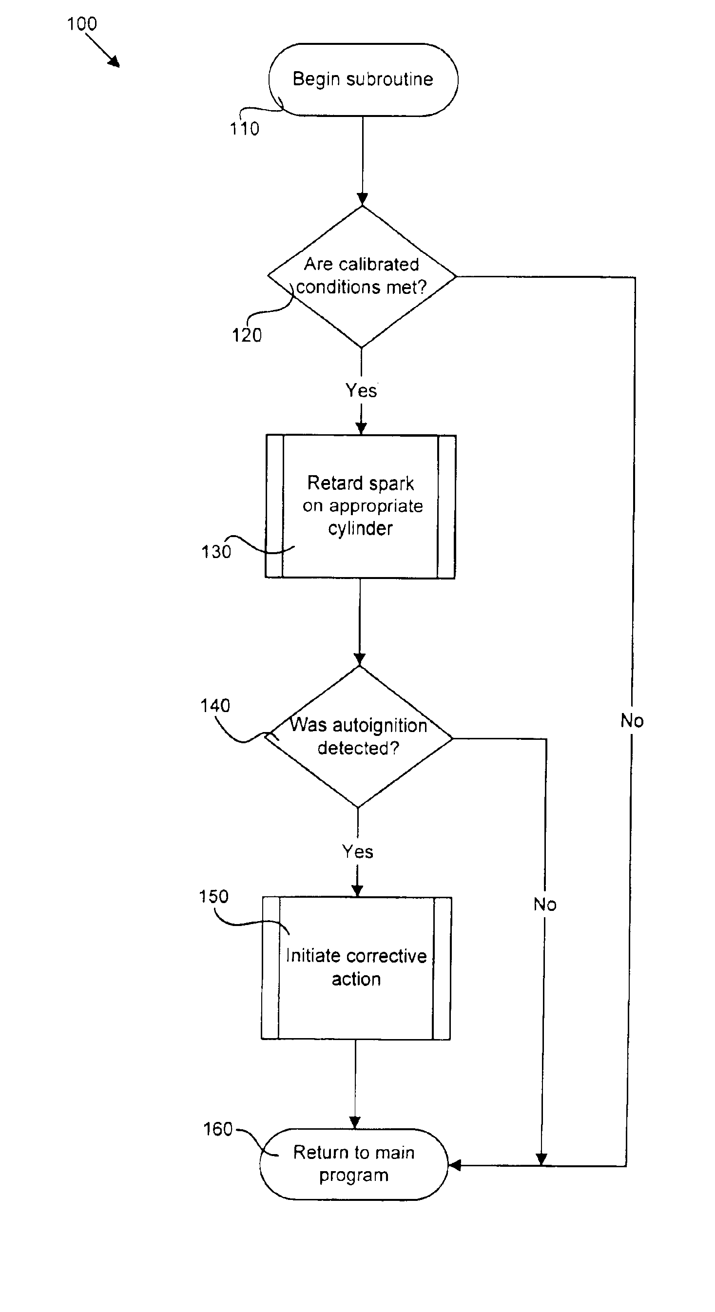
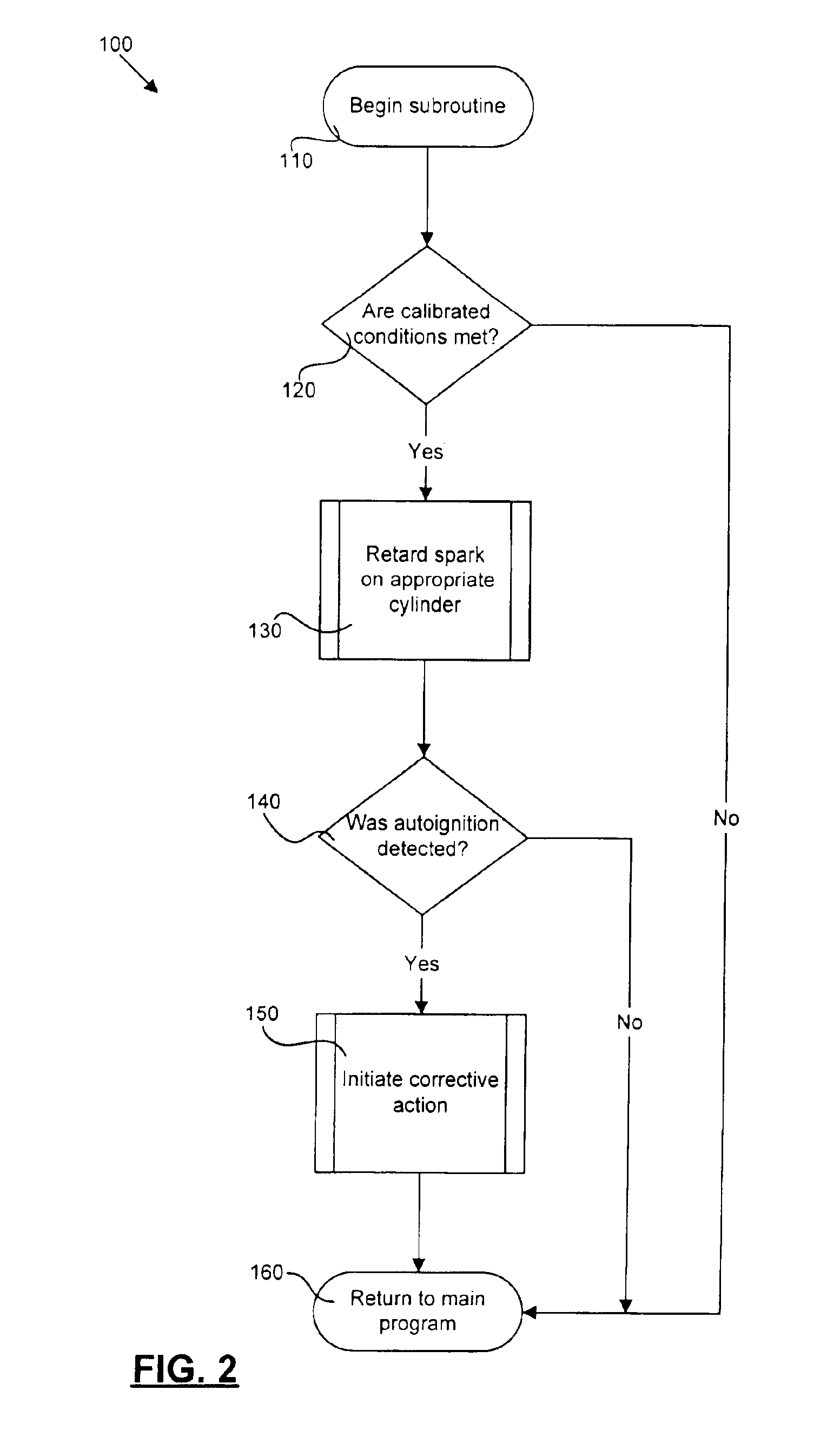
Preignition in an engine is prevented by identifying engine conditions that relate to autoignition. If one or more of the engine conditions exceed a threshold, a controller retards the spark in the engine. The controller detects whether autoignition occurs in the engine due to the retarded spark advance. If autoignition is detected, the controller corrects the one or more engine conditions by at least one of reducing a throttle opening, cutting of fuel to a cylinder, adjusting a camshaft phase, and storing a diagnostic code.

Description

FIELD OF THE INVENTION[0001]The present invention relates to electronic engine management, and more particularly to preventing preignition with electronic engine management.BACKGROUND OF THE INVENTION[0002]A typical vehicle engine relies on internal combustion within engine cylinders to provide torque. A spark generated by a spark plug ignites a mixture of air and fuel within the cylinders to cause combustion. Spark timing and control of the air / fuel mixture determine the performance of the engine.[0003]Autoignition may cause damage to the cylinders, pistons, and valves. Autoignition occurs when the air / fuel mixture combusts without spark. Ideally, the spark ignites the air / fuel mixture slightly before the piston reaches top dead center (TDC). However, when a combustion chamber or spark plug surface in a cylinder reach a sufficiently high temperature, auto ignition occurs. Preignition refers to autoignition that occurs before proper spark timing.[0004]Causes of preignition include, ...

Claims


Application Information

Patent Timeline
Patent Type & Authority Patents(United States)
IPC IPC(8): F02D43/00F02P5/00F02P5/15F02D41/00F02D41/36F02P5/152F02P17/12
CPCF02P5/1525F02P17/12F02P5/1526F02D41/0087Y02T10/46Y02T10/40
Inventor WOZNIAK, RONALD M.JACKSON, JOHN S.
Owner GM GLOBAL TECH OPERATIONS LLC
Learn More