Cigarette having porous heat transfer tube

a heat transfer tube and smoking technology, applied in the field of smoking articles, can solve the problems of reducing the flavor to some extent, the total particulate matter or tar level of the cigarette, etc., and achieve the effect of significant heat energy and extremely low pressure in the hollow tub

Inactive Publication Date: 2005-04-26
PHILIP MORRIS USA INC
View PDF10 Cites 33 Cited by
  • Summary
  • Abstract
  • Description
  • Claims
  • Application Information

AI Technical Summary

Benefits of technology

[0011]During a draw upon the cigarette, the flow in the cigarette takes place in two regions, one through the tobacco bed contained between the hollow tube and the outer cigarette wrapper paper, and the other through the burning coal and the hollow tube. Because the pressure drop in the hollow tube is extremely low compared to the pressure drop through the tobacco bed, hot air coming out of the burning coal into the hollow tube flows to the segment of the filter containing flavor capsules and delivers significant heat energy to the flavor capsules. When the end of the hollow tube near the burning coal is closed by the heat of the coal, the remaining portion of the tube toward the filter remains open and allows the flow of air into the tube as a result of its porosity and / or perforations. Heat is transferred through the hollow tube by convection from the burning coal at one end of the cigarette to the flavor capsule segment of the filter. The flavorant released by the application of this thermal energy to the flavor capsules is delivered through the remaining portion of the filter.

Problems solved by technology

This high filter efficiency and greater dilution reduces the total particulate matter or tar level of the cigarette and hence reduces the flavor to some extent.

Method used


Image

  • Cigarette having porous heat transfer tube
  • Cigarette having porous heat transfer tube
  • Cigarette having porous heat transfer tube

Examples


Embodiment Construction

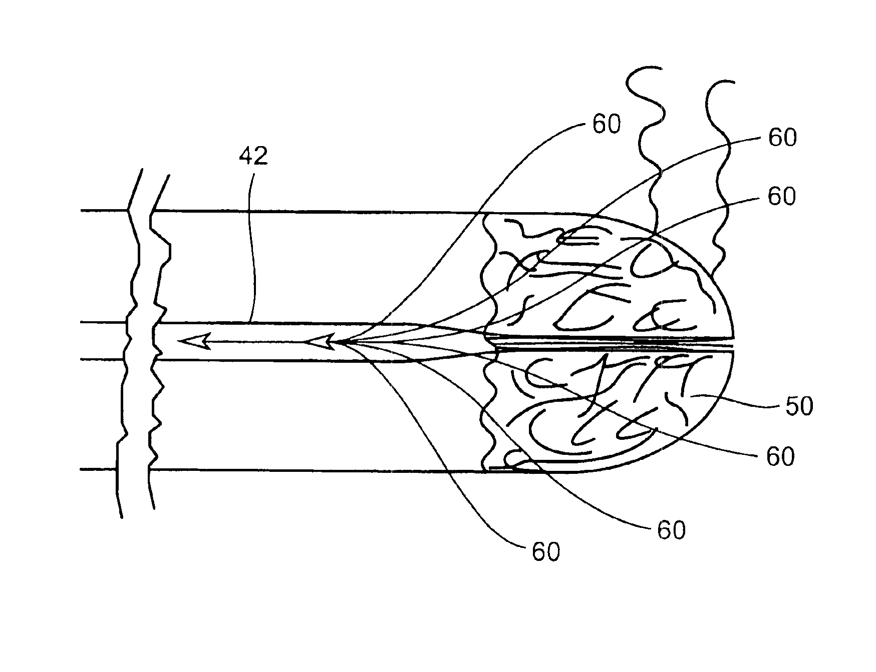
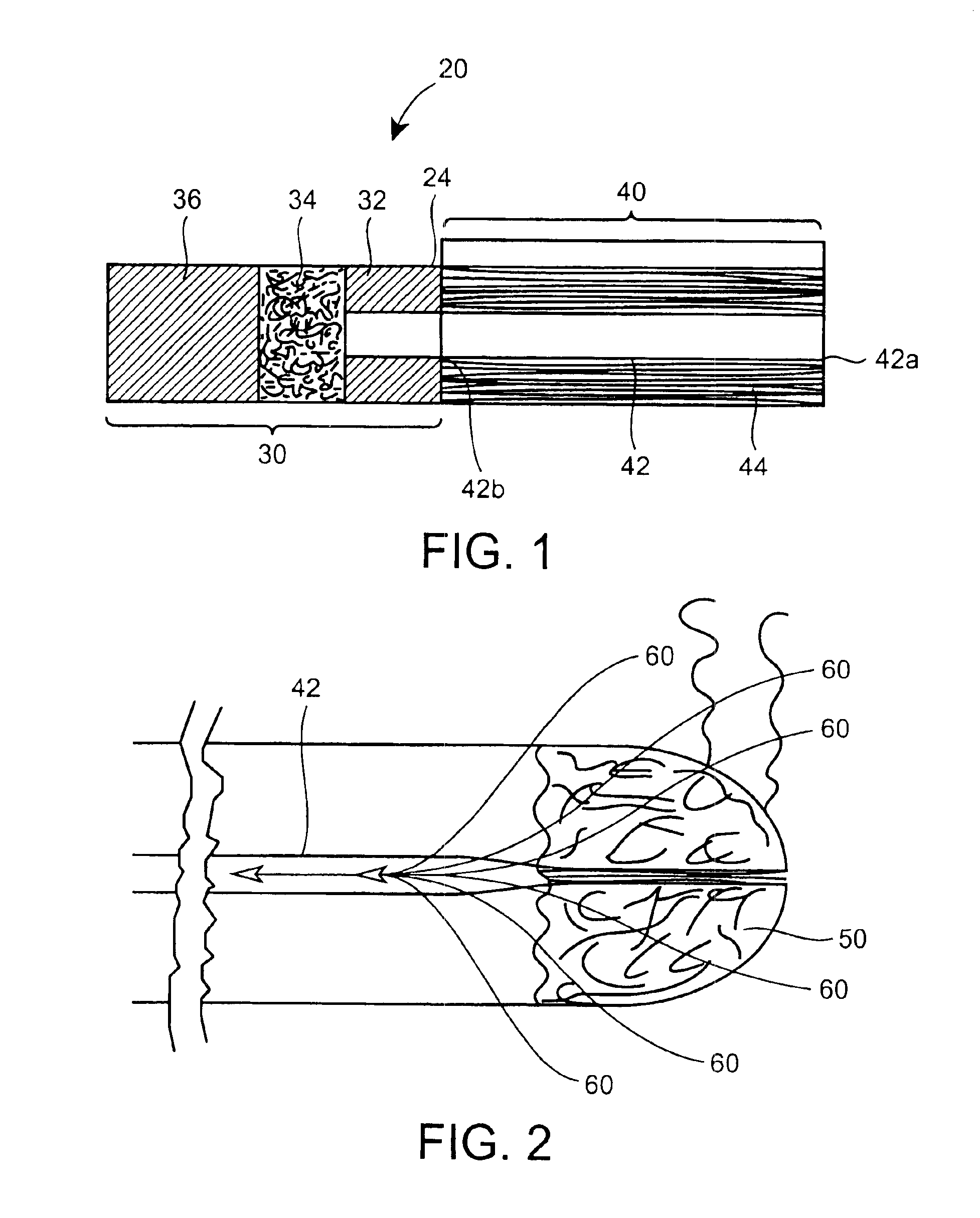
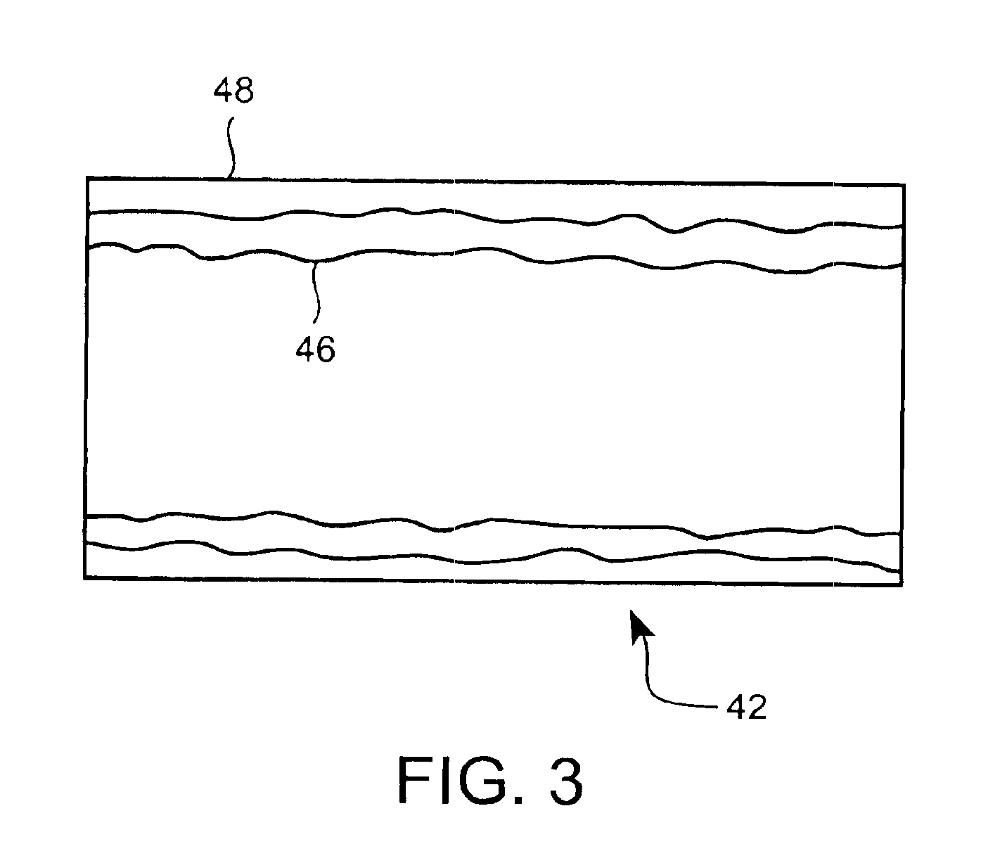
[0016]Referring initially to FIG. 1, a longitudinal cross-section of an embodiment of the invention is shown wherein a smoking article 20 includes a filter portion 30 and a cylinder of smoking material or tobacco rod 40. The cylinder of smoking material 40 can include a central hollow tube 42, surrounded by tobacco filler material 44, and an outer layer of cigarette wrapper (paper) 24 that extends from the cylinder of smoking material over the filter section and joins the filter section 30 to the cylinder of smoking material 40 in end-to-end relationship.

[0017]The central tube 42 within the cylinder of smoking material 40 preferably extends all the way to the end 42a of the cigarette opposite from the filter end of the cigarette. The end 42b of the tube 42 is preferably aligned with and abuts a hollow segment 32 of the filter portion 30.

[0018]The hollow segment 32 of the filter 30 provides a central air passageway leading from the hollow tube 42 of the cylinder of smoking material t...


PUM


Abstract

A smoking article includes a cylinder of smoking material, a filter attached to the cylinder of smoking material, and a tube of preferably porous and/or perforated material adapted to collapse at an open end upon exposure to thermal energy and preferably extending from one end portion of the smoking material to the junction of the filter and the cylinder of smoking material. Thermal energy generated by a burning portion of the tobacco filler material within the cylinder of smoking material is transferred by convection through the open portion of the tube after the end portion of the tube has collapsed closed by the heat from the burning portion of the tobacco.

Description

FIELD OF THE INVENTION[0001]This invention relates to smoking articles in general and more particularly, to a smoking article having enhanced flavor delivery.BACKGROUND OF THE INVENTION[0002]In recent years there has been a tendency in the tobacco industry to produce tobacco products, particularly cigarettes, having filters with greater filtering efficiency and higher levels of dilution. This high filter efficiency and greater dilution reduces the total particulate matter or tar level of the cigarette and hence reduces the flavor to some extent.[0003]Traditional, lit-end cigarettes comprise a cylindrical tobacco rod portion that is between 7.0 and 10.0 mm in diameter and 60 mm and 125 mm in length. The tobacco rod portion, which is composed of one or more selected types of cut tobacco, is wrapped in cigarette paper along its outer circumference. A filter, preferably of cellulose acetate or some other cellulosic material, is attached, in end-to-end relation, to the mouth end of the t...

Claims


Application Information

Patent Timeline
Patent Type & Authority Patents(United States)
IPC IPC(8): A24D1/00A24D3/04A24D3/00
CPCA24D3/048A24D1/00A24D1/002A24D3/10A24D3/0279A24D3/061A24C5/52
Inventor DANTE, HENRY M.
Owner PHILIP MORRIS USA INC
Why Eureka
Try Eureka