Die changing apparatus of molding die

a die changing and molding machine technology, applied in the field of die changing machines, can solve the problems of reducing the operational availability of the molding machine, requiring a lot of time, and extremely shortening the die changing time, so as to shorten the time required, improve the operational availability, and improve the effect of die changing operation efficiency

Inactive Publication Date: 2005-04-26
TOYOTA JIDOSHA KK
View PDF8 Cites 7 Cited by
  • Summary
  • Abstract
  • Description
  • Claims
  • Application Information

AI Technical Summary

Benefits of technology

[0026]Since the present invention is structured in the manner mentioned above, it is possible to achieve a more efficient die changing operation so as to shorten a time required for the die changing operation of the die, improve an operational availability and restrict an increase of product cost, in various kinds of molding die.
[0027]Further, in accordance with the present invention, it is possible to rapidly and securely perform the operation for drawing out the exclusive portion to the predetermined position apart from the general portion and pressing the exclusive portion existing at the predetermined position to the predetermined position within the general portion, within the molding machine in the die unclamp state, and shorten t...

Problems solved by technology

Accordingly, a whole of the die becomes heavy (196 kN (about 20 ton) for one example) and large in scale (about 2 m for one example), it is extremely troublesome to take out the die from the molding machine and it is necessary to take out and insert a tie bar connecting a fixed portion to a movable portion, so that there is a problem that an effect of shortening the die changing time is extremely small.
Further, at a time of the manual works, it is necessary to temporarily shut off a power source of the die changing apparatus completely.
The working procedure mentioned above of course requires a lot of time, and causes a decrease of operational availability in the molding machine.
Further, in many cases, a portion to be repaired is only a portion constituting a product surface in a whole of the die in most cases, and a lot of time is required for work for taking out the whole of the die from the molding machine despite that such a repair is finished in a comparatively short time.
Accordingly, t...

Method used


Image

  • Die changing apparatus of molding die
  • Die changing apparatus of molding die
  • Die changing apparatus of molding die

Examples


Embodiment Construction

[0049]A description of embodiments in accordance with the present invention will be given below with reference to the accompanying drawings. In this case, the same reference numerals are attached to the same parts and the corresponding parts to the prior art, and a detailed description will be omitted.

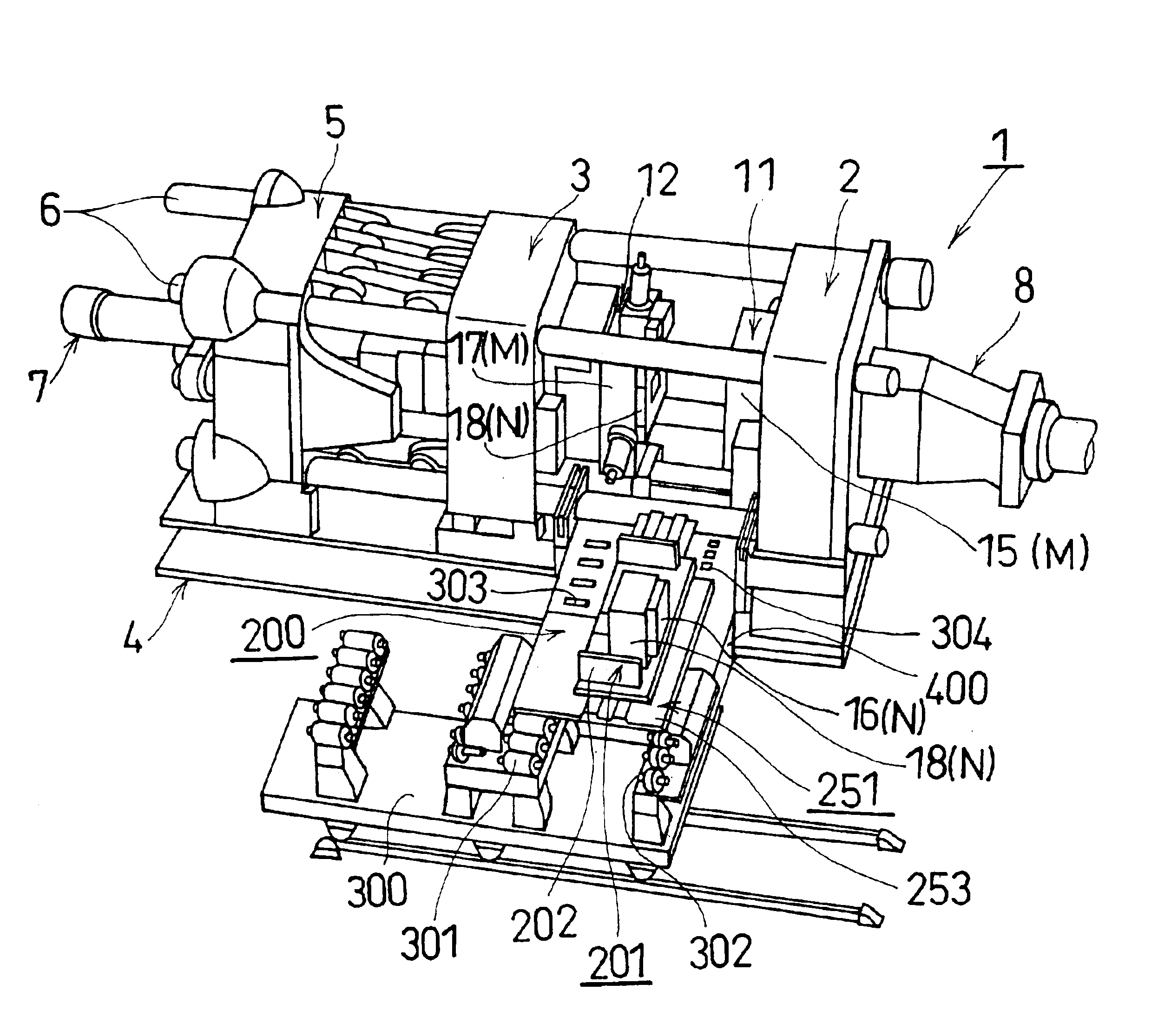
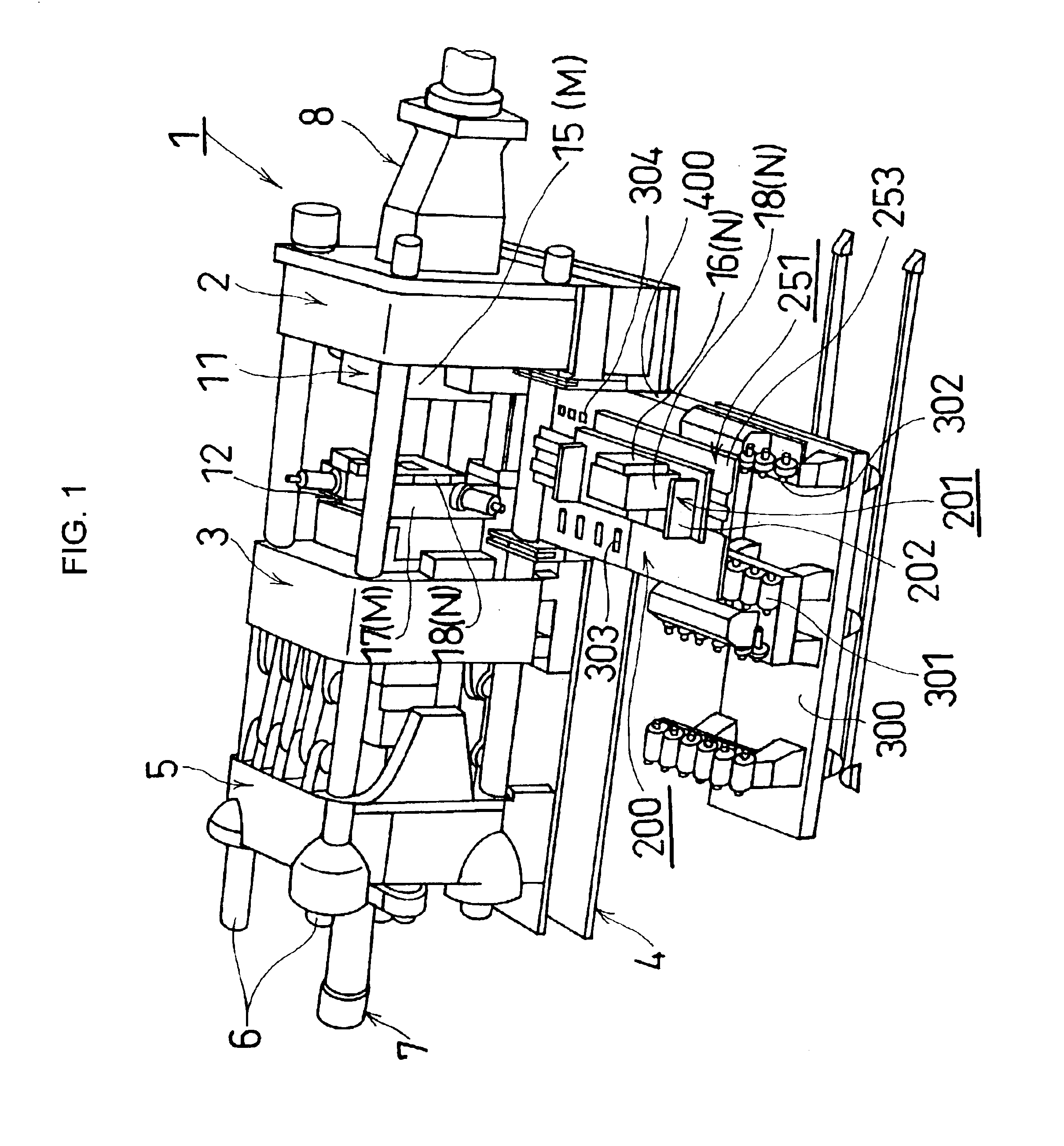
[0050]FIG. 1 shows a schematic view of an entire die casting machine 1 provided with a die changing apparatus 200 in accordance with an embodiment of the present invention. In this case, first, a description will be briefly given of a structure of the die casting machine 1. The die casting machine 1 has a fixed platen 2 for mounting a fixed die 11, and a movable platen 3 for mounting a movable die 12. The movable platen 3 is slidably guided by four tie bars 6 which are bridged between a fixed platen 2 arranged on one end portion of a stand 4 and a fixed table 5 arranged on another end portion of the stand 4, and have a extremely high rigidity, and moves apart from or close to the fixed...


PUM

PropertyMeasurementUnit
Angleaaaaaaaaaa
Timeaaaaaaaaaa

Abstract

The invention achieves a more effective die changing work, reduces a time required for performing die changing of work of a die, and improves an operational availability of a molding machine, in various kinds of molding dies. A die changing operation can be efficiently performed by drawing out an exclusive portion which is automatically attached to and detached from a general portion of a molding die, from the general portion by a feeding means and pressing the exclusive portion to the general portion. Further, the exclusive portion (an old insert) drawn out to a predetermined position from the general portion can be carried out to an outer side of a die casting machine by a carrying means, and another exclusive portion (a new insert) can be carried in to a predetermined position within the machine from the outer side thereof, within the machine in a die unclamp state. A subject to be treated by the feeding means and the carrying means in the die changing operation is only the exclusive portion, and the subject to die changing can be made compact and light in comparison with the case that a whole of the die is changed.

Description

BACKGROUND OF THE INVENTION[0001]1. Field of the Invention[0002]The present invention relates to an automatic die changing apparatus of a die for rapidly performing a die changing of a die with respect to a molding machine.[0003]2. Description of the Prior Art[0004]Conventionally, for obtaining a die cast product having a large size and a complex structure such as a cylinder block, the die requires a slide. Accordingly, a whole of the die becomes heavy (196 kN (about 20 ton) for one example) and large in scale (about 2 m for one example), it is extremely troublesome to take out the die from the molding machine and it is necessary to take out and insert a tie bar connecting a fixed portion to a movable portion, so that there is a problem that an effect of shortening the die changing time is extremely small.[0005]Further, a part of some work, for example, work for attaching and detaching a hose for a die cooling water and a cable for operation control with respect to the die are manua...

Claims


Application Information

Patent Timeline
IPC IPC(8): B22D17/22B29C45/17
CPCB29C45/1756B22D17/229
Inventor MATSUURA, YOSHIKIKATO, TSUKASAHIRAI, TAKASHI
Owner TOYOTA JIDOSHA KK
Why Eureka
Try Eureka