Machine tool

a technology of machine tools and tools, applied in the field of machine tools, can solve the problems of imposing a great burden on the operator, unable to efficiently perform the machining of the workpiece in a short time, and a great effort and time, and achieve the effects of efficient machined work, short time, and reduced labor intensity

Inactive Publication Date: 2005-04-26
DMG MORI CO LTD
View PDF21 Cites 17 Cited by
  • Summary
  • Abstract
  • Description
  • Claims
  • Application Information

AI Technical Summary

Benefits of technology

[0010]With this arrangement, when the workpiece is to be fixed to the workpiece spindle in the machine tool, the centering jig is taken out of a tool magazine and attached to the tool spindle, and the workpiece is automatically centered by the centering jig by moving the tool spindle on the basis of the run-out of the workpiece measured by the run-out measuring device. Therefore, the operator does not have to manually perform the troublesome workpiece centering operation, which is required in the case of the conventional machine tool, whenever the workpiece is mounted on the workpiece spindle. This alleviates the burden on the operator.
[0011]According to a second aspect of the present invention, there is provided a machine tool adapted to fix a workpiece to a workpiece spindle by non-self-aligning clamp means, the machine tool comprising: a tool magazine which accommodates a plurality of tools; an automatic tool changer for exchanging a tool between the tool magazine and a tool spindle; and a run-out measuring device for measuring a run-out of the workpiece resulting from off-center of the workpiece mounted on the workpiece spindle; wherein a centering jig to be attached to the tool spindle is accommodated in the tool magazine; wherein, when the workpiece is to be fixed to the workpiece spindle by the clamp means, the centering jig is taken out of the tool magazine and attached to the tool spindle by the automatic tool changer, and the tool spindle is moved on the basis of the run-out of the workpiece measured by the run-out measuring device to center the workpiece by the centering jig. With this arrangement, a process sequence from the mounting of the workpiece to the machining of the workpiece can sequentially be performed. Hence, the workpiece can efficiently be machined in a short time.

Problems solved by technology

This requires great effort and time, thereby imposing a great burden on the operator in a preparatory operation.
In addition, the machining of the workpiece cannot efficiently be performed in a short time.

Method used


Image

  • Machine tool
  • Machine tool
  • Machine tool

Examples


Embodiment Construction

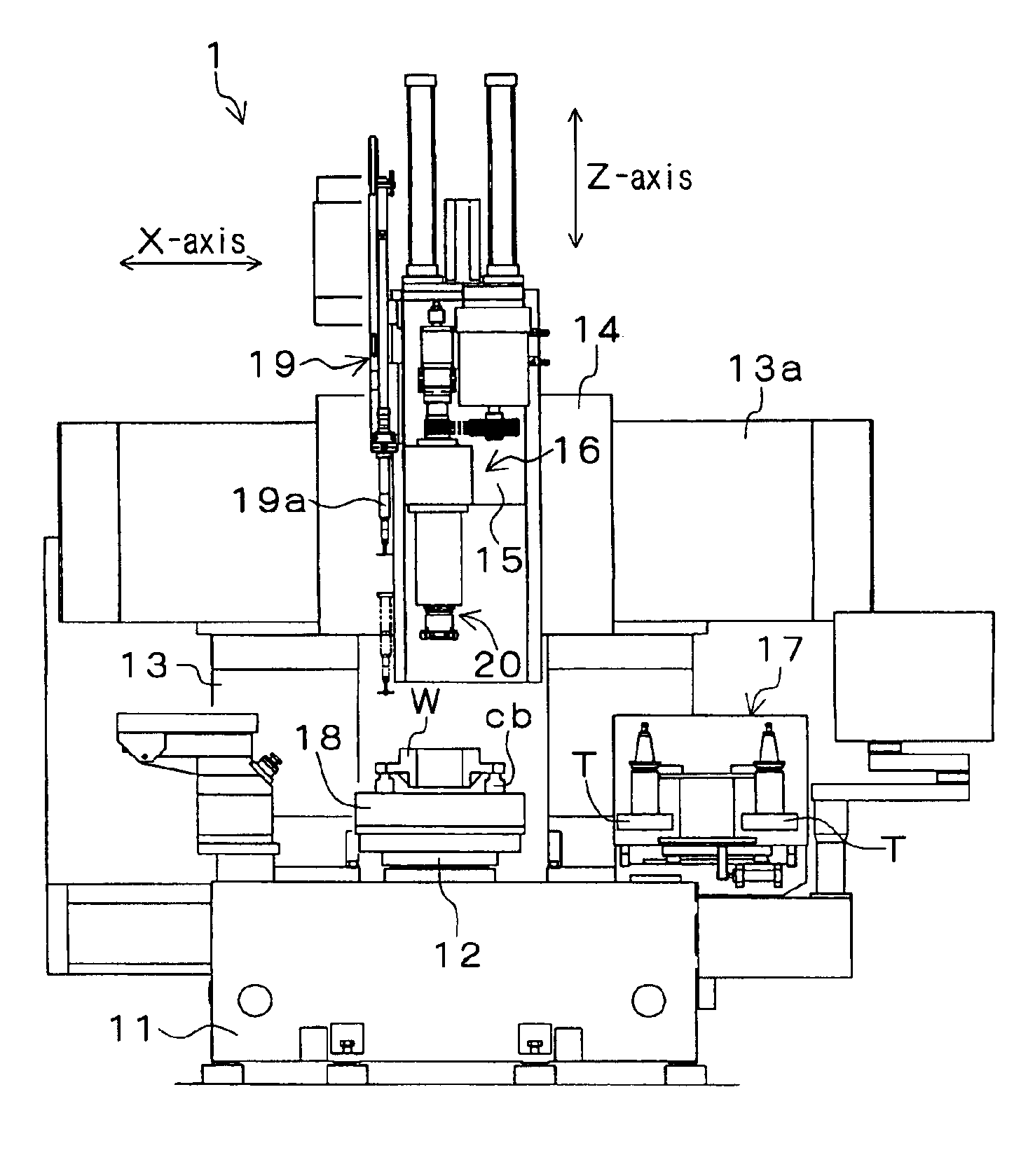
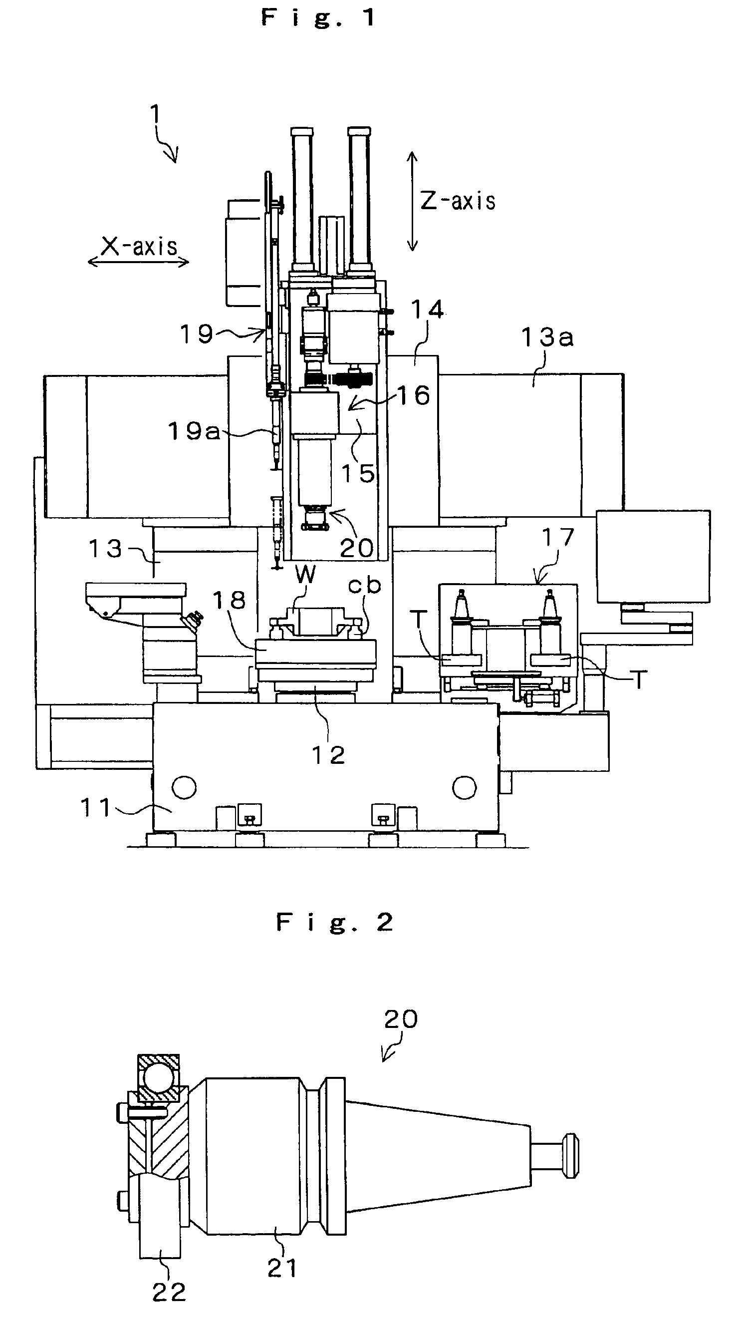
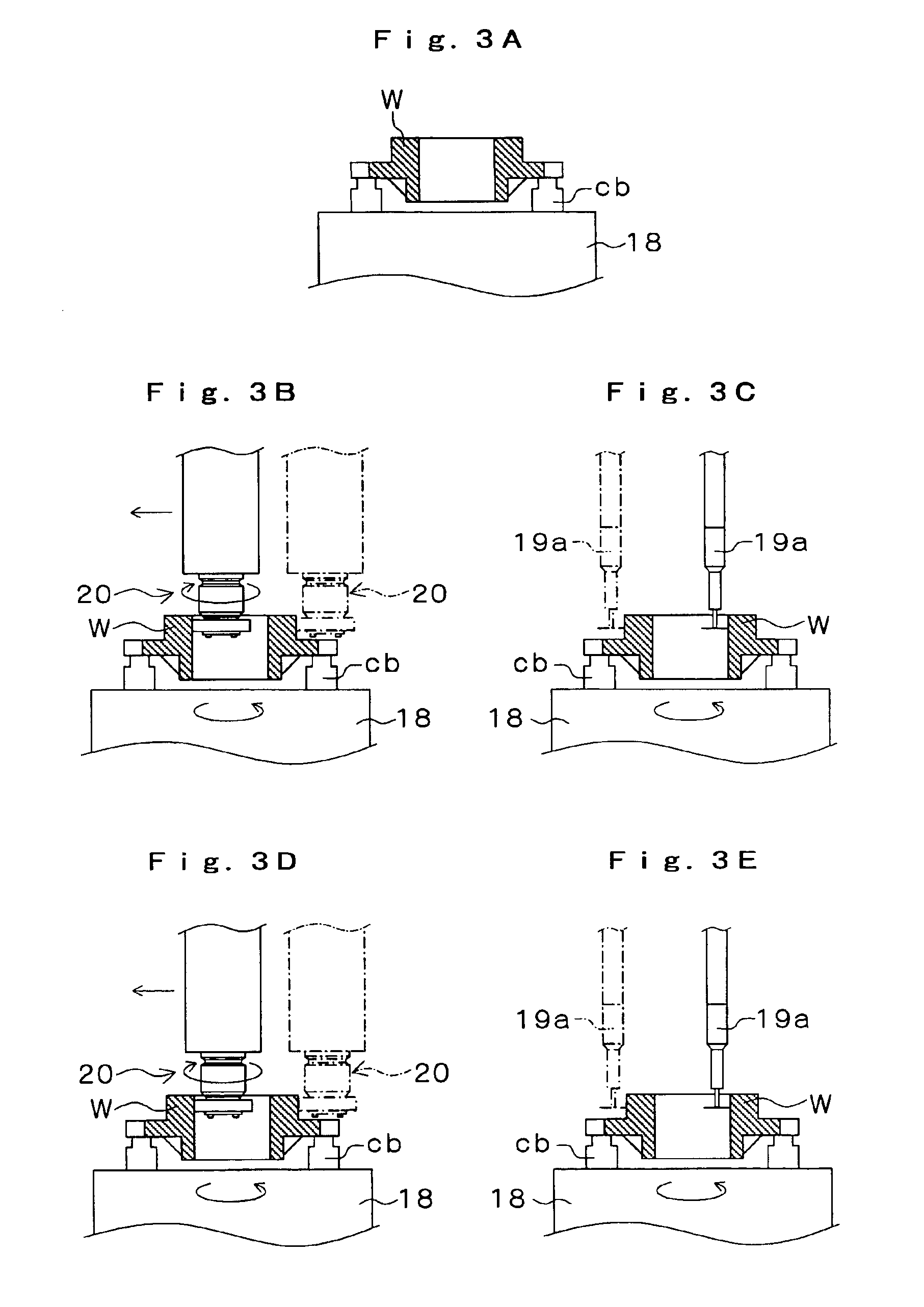
[0017]An embodiment of the present invention will hereinafter be described with reference to the attached drawings. As shown in FIG. 1, the vertical grinder 1 includes a bed 11, a workpiece spindle 12 provided on the bed 11 as extending vertically (along the Z-axis) a column 13 provided upright on a rear portion of the bed 11, a slide member 14 slidable laterally (along the X-axis) on a slideway 13a provided on the column 13, a tool spindle head 16 provided on a support base 15 movable vertically (along the Z-axis) on a slideway provided on a front face of the slide member 14, and an armless automatic tool changer 17 for automatically exchanging a tool T between a tool spindle and a tool magazine which accommodates a plurality of tools (grinding wheels) to be attached to the tool spindle. A non-self-aligning electromagnetic chuck 18 for clamping a workpiece W is provided on an upper end of the workpiece spindle 12.

[0018]A run-out measuring device 19 having a detector 19a movable ver...


PUM

PropertyMeasurementUnit
attractive forceaaaaaaaaaa
timeaaaaaaaaaa
speedaaaaaaaaaa

Abstract

A machine tool comprises: a workpiece spindle (12) having an electromagnetic chuck (18) provided on an upper end thereof for clamping a workpiece (W), and extending along the Z-axis; a tool magazine which accommodates a tool (T) and a centering jig (20); an automatic tool changer (17) for exchanging the tool (T) between the tool magazine and a tool spindle; and a run-out measuring device (19) for measuring a run-out of the workpiece (W) placed on the electromagnetic chuck (18); wherein a workpiece correction distance is calculated on the basis of the run-out of the workpiece (W) measured by the run-out measuring device (19) before the workpiece (W) is clamped by the electromagnetic chuck (18), and a workpiece centering operation is automatically performed by the centering jig (20) attached to the tool spindle until the run-out of the workpiece (W) falls within an allowable range.

Description

BACKGROUND OF THE INVENTION[0001]1. Field of the Invention[0002]The present invention relates to a machine tool which is adapted to fix a workpiece to a workpiece spindle by non-self-aligning clamp means such as a magnetic chuck or a face-clamp and, particularly, to a machine tool having an automatic workpiece centering function.[0003]2. Description of Related Art[0004]In a machine tool such as a CNC vertical grinder having a vertical workpiece spindle for rotating a workpiece, for example, a magnetic chuck for clamping the workpiece by utilizing an attractive force of an electromagnet is provided on an upper end of the workpiece spindle. The workpiece is machined, while the workpiece spindle is rotated with the workpiece being clamped by the magnetic chuck.[0005]Meanwhile, a mechanical chuck including a plurality of chuck claws movable radially inwardly and outwardly of the workpiece spindle for clamping the workpiece has a self-aligning function such that the center of the workpie...

Claims


Application Information

Patent Timeline
Patent Type & Authority Patents(United States)
IPC IPC(8): B23Q17/22B23Q3/18B23B25/06B24B5/00B24B5/02B24B41/06B24B49/10
CPCB23Q3/183B23Q17/2291B23Q3/152B23Q2230/002Y10T409/306944Y10T483/14Y10T409/309408Y10T409/30952Y10T409/303864
Inventor WATANABE, NOBORU
Owner DMG MORI CO LTD
Why Eureka
Try Eureka