Matrix and method of producing said matrix

a matrix and matrix technology, applied in the field of matrix and matrix production, can solve the problems of reducing the production time, affecting the production efficiency, and affecting the quality of the matrix, so as to reduce the production time, enhance the replication capacity, and produce more simply

Inactive Publication Date: 2005-04-26
GYROS
View PDF19 Cites 116 Cited by
  • Summary
  • Abstract
  • Description
  • Claims
  • Application Information

AI Technical Summary

Problems solved by technology

It has been found that in forming a matrix the metal build-up on the microstructure-carrying surface of a master results in minor defects or irregularities on the rear side of the matrix, which irregularities are caused by the microstructure, and that it is necessary to subsequently smooth said rear side in order for it to lie in effective abutment, e.g. flat, on a flat surface on the mould half that supports it in the pressing machine used.
The process of applying a truly thick layer of metal as in the case of deeper microstructures takes a relatively long time to achieve, for instance it will take from 10 to 20 hours to apply a nickel cladding which is a few millimetres thick.
Furthermore, it takes considerable time to grind and / or polish down the metallic rear side to a smooth surface.
However, in principle, a metallic layer takes longer to grow with a pulsed field than with a direct current.
It is herewith obvious that because of the matrices' and the mould halves' large heat storing capacity, large heat and cooling transport system are required, which lead to a consequently slow manufacturing speed.
Thus, it has been suggested to form channels in the mould halves and supply hot water respectively cold water through these, but because of the high pressure which exists inside the mould cavity it is technically difficult to position them optimally close to the matrix.

Method used


Image

  • Matrix and method of producing said matrix
  • Matrix and method of producing said matrix
  • Matrix and method of producing said matrix

Examples


Embodiment Construction

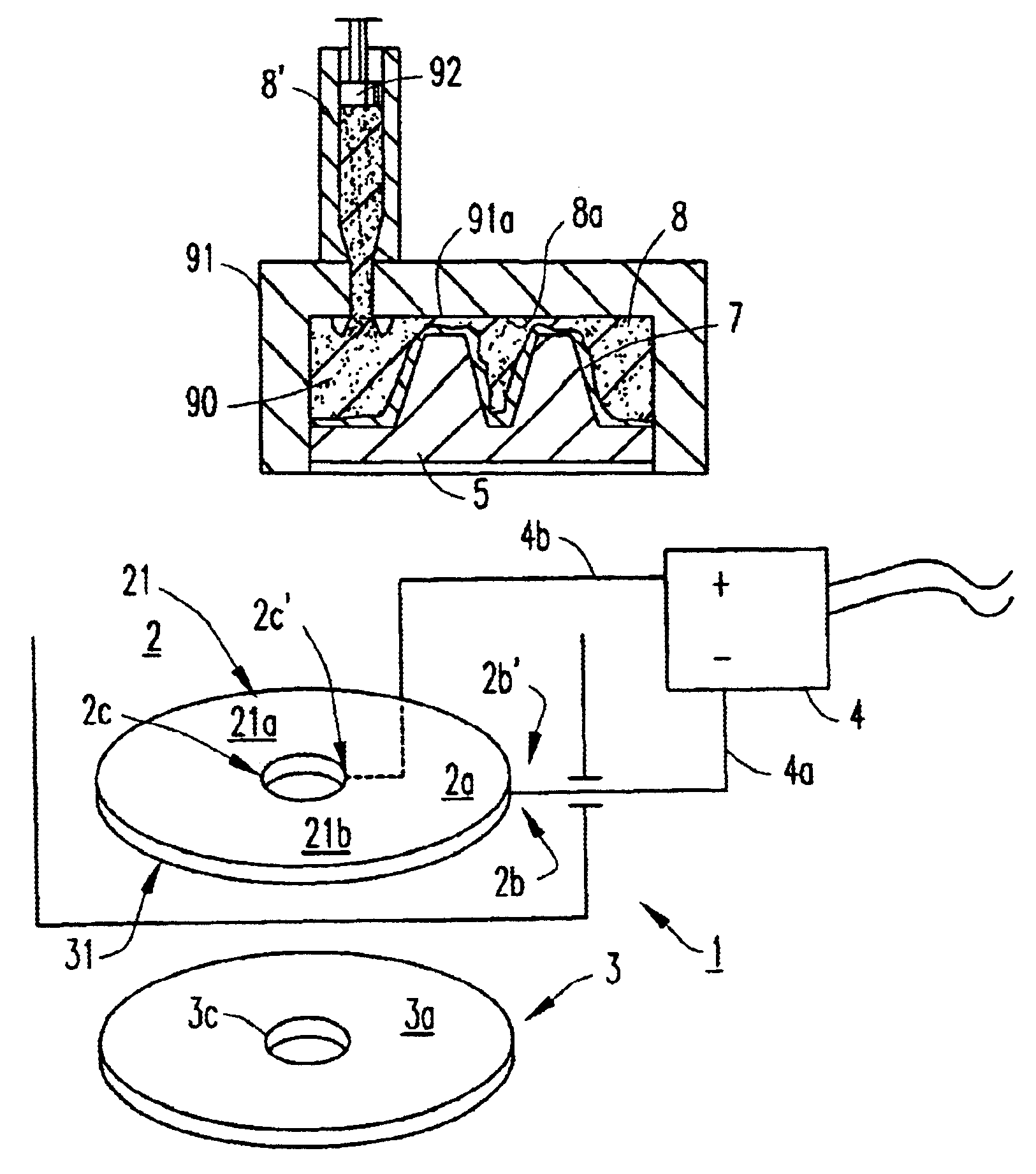
[0130]The present invention relates to a method of producing a matrix 2, in particular a matrix 2 adapted for use in a compression moulding, embossing, injection moulding and / or other plastic element-producing press 1

[0131]One surface of the matrix 2 is given a negative microstructure 2a that can be replicated as a positive microstructure 3a on a plastic element 3 in the injection moulding press 1.

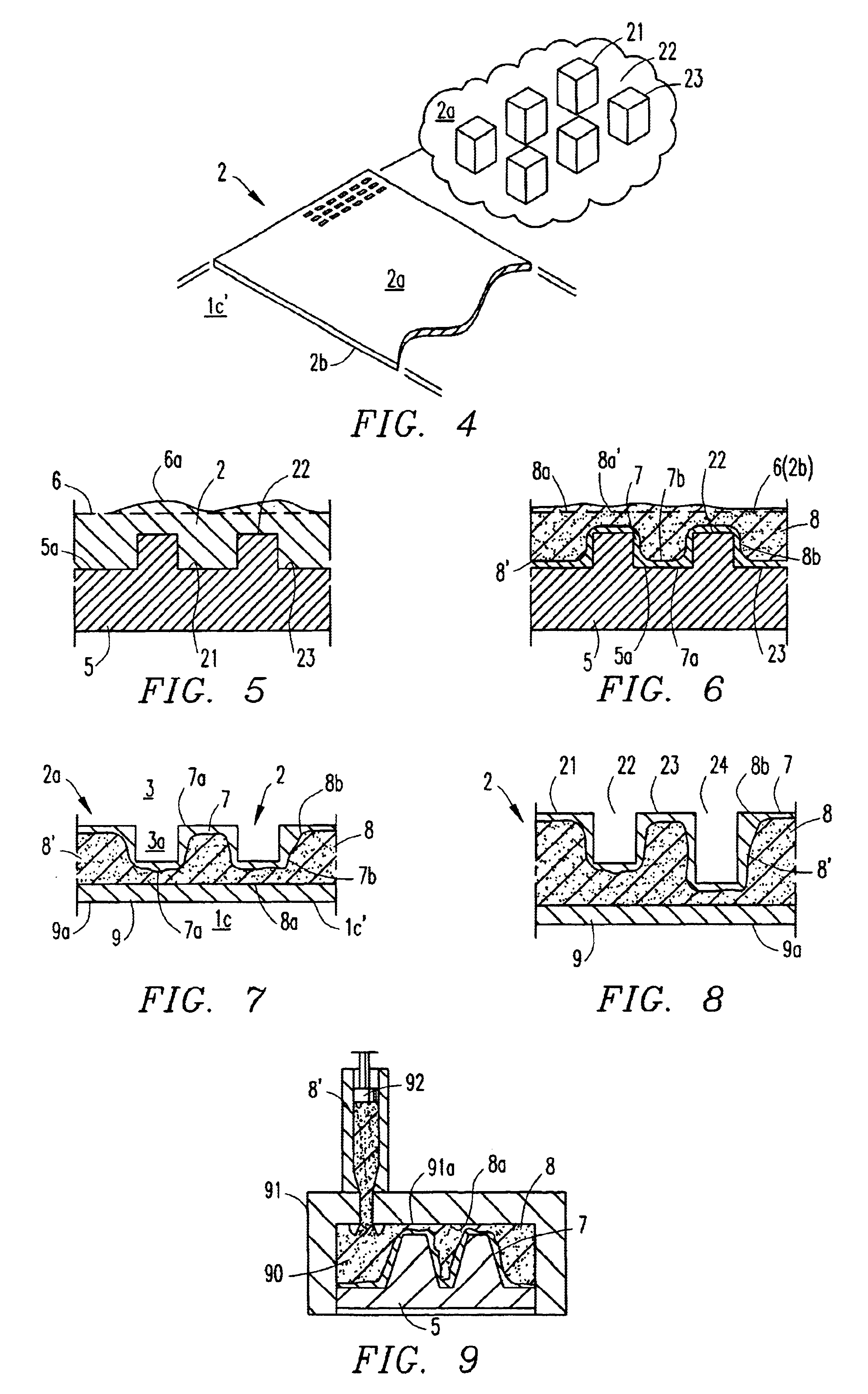
[0132]The method by means of which the matrix 2 is produced will be described in more detail below with reference to FIG. 6.

[0133]For the sake of simplicity, the following description assumes that solely the moveable mould half is provided with a matrix 2 that has a microstructure 2a, although the person skilled in this art will realise that the fixed mould half may also be provided with such a matrix.

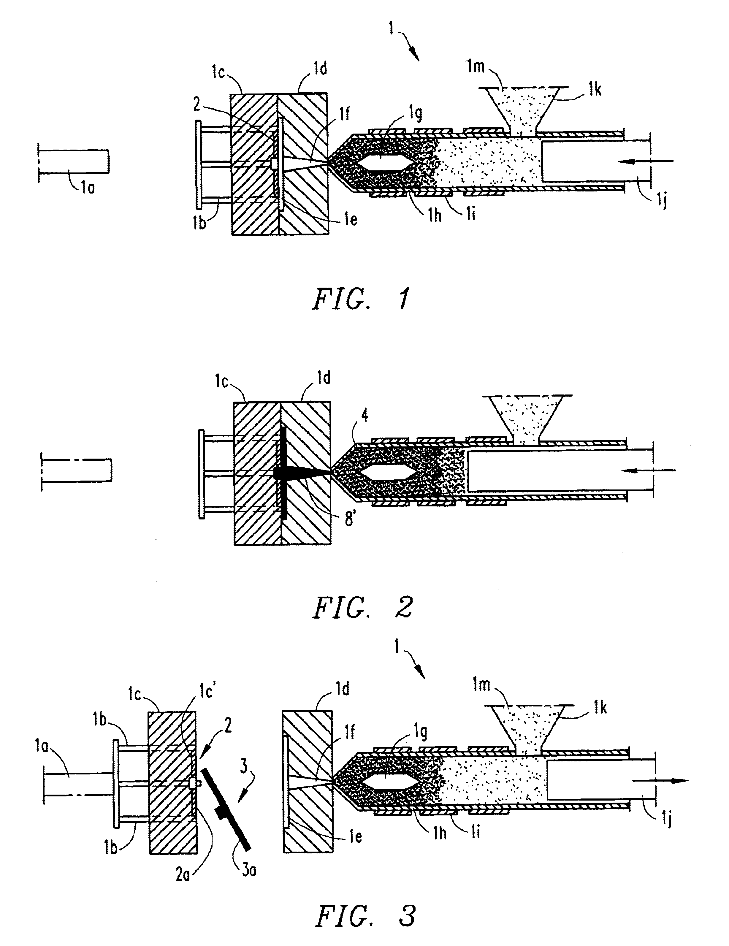
[0134]Thus, FIGS. 1-3 illustrate schematically an injection moulding press I that includes an ejector rod 1a, a number (3) of ejector pins 1b, a moveable mould 1c and a fixed mould 1d.

[0135]...


PUM

PropertyMeasurementUnit
thicknessaaaaaaaaaa
thicknessaaaaaaaaaa
thicknessaaaaaaaaaa

Abstract

The invention relates to a matrix suitable for use in the replication of a plastic element having a positive microstructure, comprising a first wear-resistant layer that is supported by a carrier element, wherein the matrix comprises a heating means for supplying electrical heat energy through the wear-resistant layer or carrier element. The invention further relates to a plastic element producing machine and a method for the manufacture of a plastic element having a surface with a positive microstructure.

Description

[0001]This is a continuation application of application Ser. No. 09 / 554,530 filed on Jul. 19, 2000 now U.S. Pat. No. 6,454,970, which is a 371 of PCT / SE99 / 01858, filed Oct. 14, 1999.FIELD OF INVENTION[0002]The present invention relates to a method of producing a matrix that can be used in a compression moulding, embossing, injection moulding and / or other plastic element-producing machine. In particularly the present invention relates to a matrix having a surface, or a part of said surface, which is provided with a negative microstructure that can be replicated as a positive microstructure, on a surface of a plastic element, such as a compact disc (CD) formed in such a machine.[0003]The invention also relates to a matrix manufactured by said method, the use of said matrix to form a plastic element and the plastic element so formed.DEFINITIONS[0004]In the following, the expression “positive surface structure” shall be understood to mean the surface structure (including topographic sur...

Claims


Application Information

Patent Timeline
Patent Type & Authority Patents(United States)
IPC IPC(8): B29C33/02B29C33/42B29C33/56B29C45/26G11B7/26B29C33/40B29C59/04B29K63/00B29K105/16B29L17/00
CPCB29C33/02B29C33/424B29C33/565G11B7/263B29C45/2632Y10S425/81B29C2045/2634B29L2017/005
Inventor OHMAN, PER OVELUNDBLADH, LARS RUNE
Owner GYROS
Why Eureka
Try Eureka