Variable type antenna matching circuit

a technology of antenna matching and variable type, applied in the field of portable telephone terminals, can solve the problems of interference with a reduction in circuit size, low degree of freedom in design, and deterioration of antenna efficiency

Inactive Publication Date: 2005-04-26
NEC CORP
View PDF10 Cites 41 Cited by
  • Summary
  • Abstract
  • Description
  • Claims
  • Application Information

AI Technical Summary

Benefits of technology

[0006]It is an object of the present invention to provide a variable type antenna matching circuit with a simple circuit arrangement which can provide impedance matching between an antenna and a transmission / reception radio circuit in accordance with a change in the shape of the housing of a portable terminal.
[0007]It is another object of the present invention to provide a variable type antenna matching circuit which can improve the degree of freedom in design.
[0008]It is still another object of the present invention to provide a variable type antenna matching circuit which can realize miniaturization of a radio terminal.

Problems solved by technology

For this reason, in a folding telephone terminal, impedance mismatching occurs between the antenna and the transmission / reception radio circuit between when the terminal is folded (e.g., the incoming wait state) and when the terminal is unfolded (e.g., the speech communication or operation state), resulting in deterioration in antenna efficiency.
Since the portable terminal requires a plurality of circuits with circuit constants corresponding to different impedances, the degree of freedom in design is low.
For example, preparing many matching circuits will interfere with a reduction in circuit size.

Method used


Image

  • Variable type antenna matching circuit
  • Variable type antenna matching circuit
  • Variable type antenna matching circuit

Examples


first embodiment

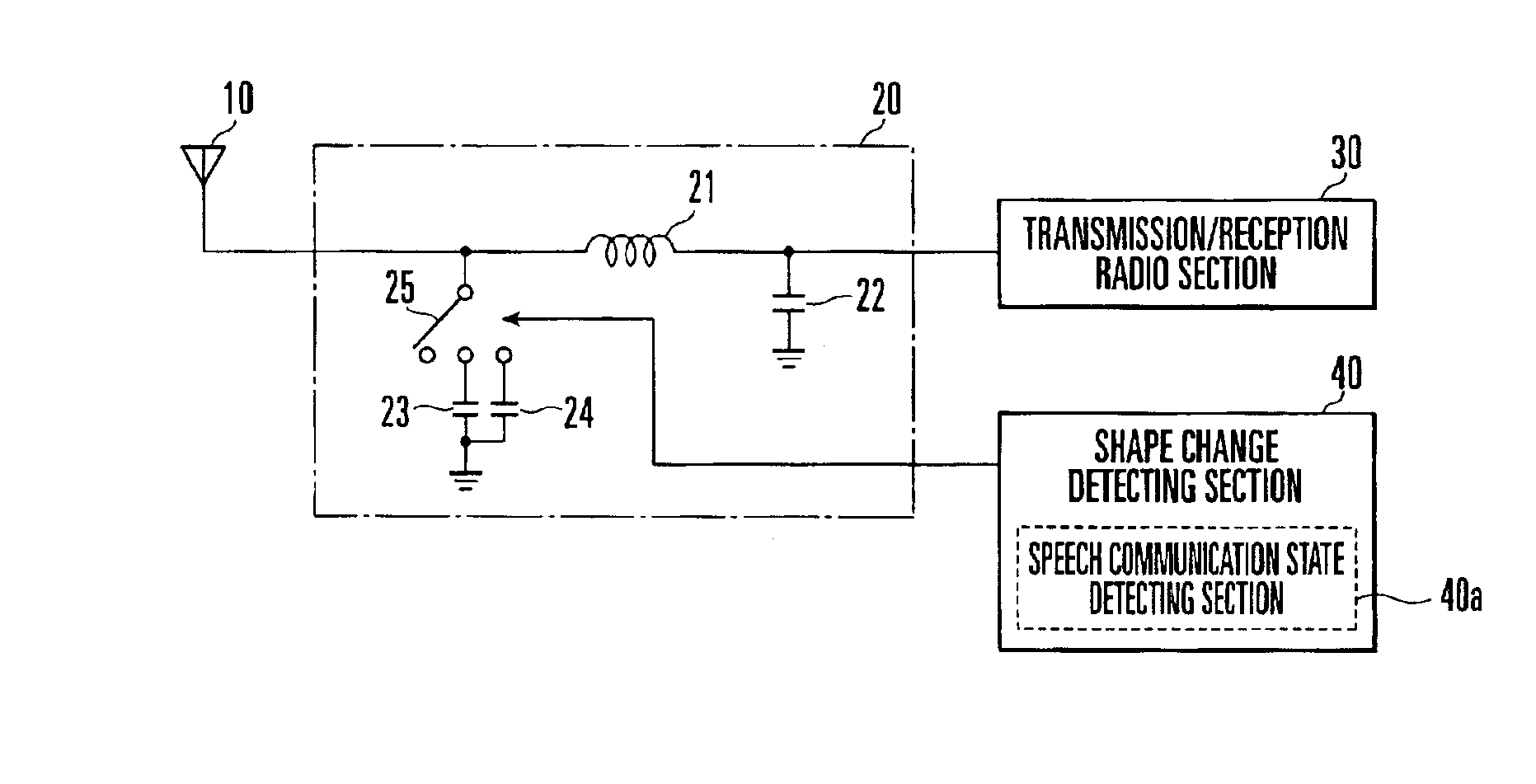
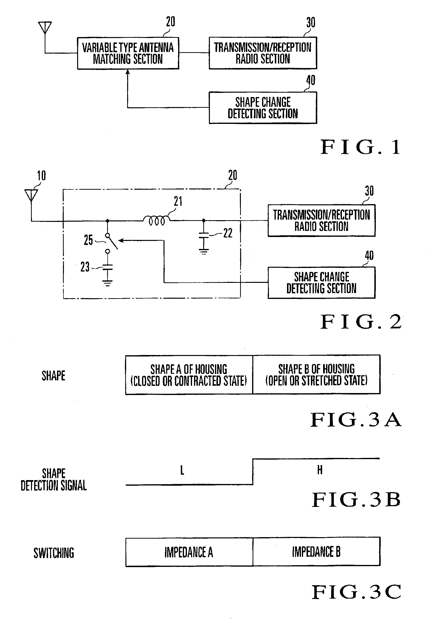
[0017]A portable radio terminal according to the present invention includes an antenna 10, a variable type antenna matching section 20 connected to the antenna 10, and a transmission / reception radio section 30 and shape change detecting section 40 which are connected to the variable type antenna matching section 20.

[0018]The variable type antenna matching section 20 is formed from a variable type antenna matching circuit and set between the antenna 10 and the transmission / reception radio section 30. The variable type antenna matching section 20 variably switches its impedance constants to cope with a change in the input impedance of the antenna due to a shape change on the basis of an output from the shape change detecting section 40 which detects a change in the shape of the housing of the portable radio terminal.

[0019]One terminal and the other terminal of the variable type antenna matching section 20 are respectively connected to the antenna 10 and transmission / reception radio se...

second embodiment

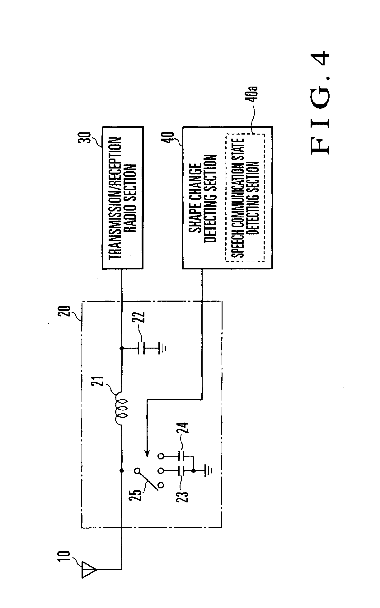
[0036]In the variable type antenna matching section 20 the shape change detecting section 40 has a speech communication state detecting section 40a which detects whether or not the portable radio terminal is in the speech communication state.

[0037]The shape change detecting section 40 selects one of the capacitor connection states in accordance with a detection result indicating one of three states, i.e., the state wherein the housing is closed, the state wherein the housing is open and speech communication is not being performed, and the state wherein the housing is open and speech communication is being performed.

[0038]In a speech communication state, the housing and antenna are located near the head of the user. When the portable terminal is used only to transmit / receive data such as messages, the terminal is used while the antenna is located near the ground surface.

[0039]The second embodiment copes with a case wherein the antenna exhibits different impedances and hence differen...


PUM


Abstract

A variable type antenna matching circuit includes an antenna, shape change detecting section, transmission / reception radio section, and variable type antenna matching section. The shape change detecting section detects a change in the shape of the housing of a portable terminal. The transmission / reception radio section transmits and receives signals. The variable type antenna matching section changes the input impedance between the antenna and the transmission / reception radio section in accordance with an output signal from the shape change detecting section.

Description

BACKGROUND OF THE INVENTION[0001]The present invention relates to a portable telephone terminal and, more particularly, to a portable telephone terminal or other types of portable terminals which can change their shapes by stretching or folding their housings. The present invention can also be applied to a circuit which provides input impedance matching for an antenna in accordance with a change in the input impedance of the antenna when the shape of a housing is changed.[0002]In a portable telephone terminal, in order to optimize the radiation efficiency of an antenna, an impedance matching circuit is arranged between the antenna and a transmission / reception radio circuit. This impedance matching circuit provides impedance matching.[0003]The shape of the housing of a folding portable telephone terminal changes as it is folded or unfolded, and hence the input impedance of the antenna changes. For this reason, in a folding telephone terminal, impedance mismatching occurs between the ...

Claims


Application Information

Patent Timeline
Patent Type & Authority Patents(United States)
IPC IPC(8): H01Q1/24H03H7/38H03H7/40H04B1/38H04B1/3822H04B1/40H04B7/26H04M1/00H04M1/76H04W16/28H04W88/02
CPCH01Q1/241H04B1/403H04B1/18H03H7/40
Inventor KURIHARA, KAZUHIRO
Owner NEC CORP
Why Eureka
Try Eureka