Scanning optical system and image forming apparatus using the same
an optical system and scanning technology, applied in the field of scanning optical systems and image forming apparatuses, can solve the problems of difficult to apply anti-reflection coating on the lens surface from technical and cost points of view, affecting the effect of optical surface reflection, and reducing the density of the optical surfa
- Summary
- Abstract
- Description
- Claims
- Application Information
AI Technical Summary
Benefits of technology
Problems solved by technology
Method used
Image
Examples
first embodiment
[0069](First Embodiment)
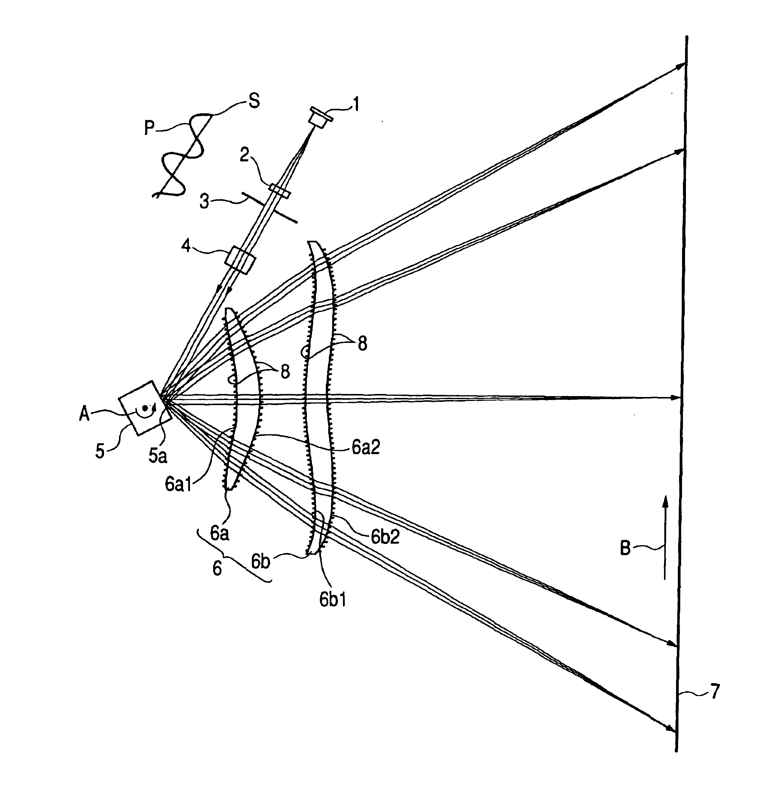
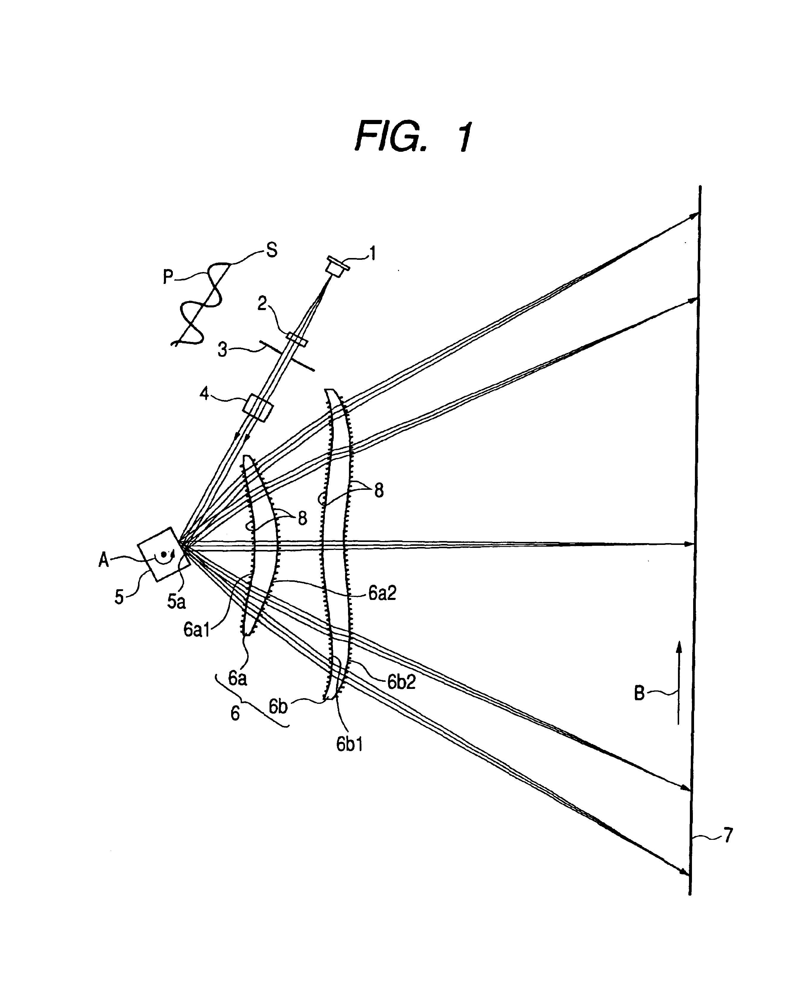
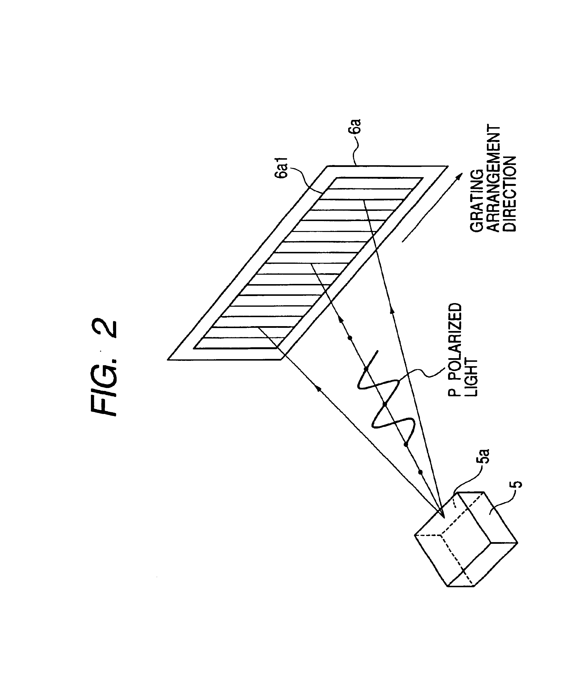
[0070]A first embodiment of the present invention will be described with reference to FIGS. 1 to 6. FIG. 1 is a main part sectional view in a main scanning direction (main scanning sectional view), showing a scanning optical system (scanning optical apparatus) according to the first embodiment of the present invention. FIG. 2 is a main part schematic view showing a light flux (P polarized light) incident into a fine structural grating.
[0071]Here, the main scanning direction indicates a direction perpendicular to the rotational axis of a deflection unit (direction of a light flux which is reflected and deflected (which is deflected for scanning) by the deflection unit). A sub scanning direction indicates a direction parallel to the rotational axis of the deflection unit. In addition, a main scanning section indicates a plane which is parallel to the main scanning direction and includes the optical axis of the scanning optical unit. A sub scanning section indic...
second embodiment
[0126](Second Embodiment)
[0127]Next, a second embodiment of the present invention will be described with reference to FIG. 8. FIG. 8 shows an optical characteristic (S polarized light) of the second embodiment of the present invention.
[0128]In this embodiment, structures different from the above-mentioned first embodiment are that (I) the light source unit 1 is placed such that a light flux incident into the scanning lens system 6 is mainly made incident as S polarized light and (II) the conditional expressions (3) and (4) related to the fine structural grating 8 are set according to the placement of the light source unit 1. Other structures and optical actions are substantially the same as the first embodiment, so that the same effect is obtained.
[0129]In other words, in this embodiment, when a light flux incident. into the fine structural grating 8 is substantially S polarized light, respective elements are set so as to satisfy conditions of
0.35λ≦h (3) and
0.80h / P (4).
[0130]Next,...
third embodiment
[0143](Third Embodiment)
[0144]FIG. 9 is a main part sectional view in a main scanning direction (main scanning sectional view), according to a third embodiment of the present invention. FIG. 10 shows a relationship between an incident angle and reflectance in the third embodiment of the present invention. In FIG. 9, the same reference numerals are provided to the same elements as shown in FIG. 1.
[0145]In this embodiment, structures different from the above-mentioned first embodiment are that (I) the light source unit 1 is composed of at least two light source sections 1a and 1b emitting different polarized light fluxes, (II) a beam combining unit 7 for combining the polarized light fluxes on different optical paths is provided between the light source unit 1 and the deflection unit 5, and (III) the conditional expressions (5) and (6) related to the fine structural grating 8 are set according to the arrangements of the light source sections 1a and 1b and the beam combining unit 7. Ot...
PUM
 Abstract
Description
Claims
Application Information
 - R&D
- Intellectual Property
- Life Sciences
- Materials
- Tech Scout
- Unparalleled Data Quality
- Higher Quality Content
- 60% Fewer Hallucinations
Browse by: Latest US Patents, China's latest patents, Technical Efficacy Thesaurus, Application Domain, Technology Topic, Popular Technical Reports.
© 2025 PatSnap. All rights reserved.Legal|Privacy policy|Modern Slavery Act Transparency Statement|Sitemap|About US| Contact US: help@patsnap.com


