Optical element and optical scanning device using the same

a scanning device and optical element technology, applied in the field of optical element and optical scanning device using the same, can solve the problems of difficult application of anti-reflection coating to the lens surface of a plastic lens, insufficient disclosure of arrangement of two-dimensionally arranged gratings, and insufficient disclosure of lens surface anti-reflection coating, etc., to achieve the effect of reducing fresnel (surface) reflection and reducing fresnel reflection

Active Publication Date: 2008-04-22
CANON KK
View PDF2 Cites 2 Cited by
  • Summary
  • Abstract
  • Description
  • Claims
  • Application Information

AI Technical Summary

Benefits of technology

[0021]An object of the present invention is to provide an optical element capable of reducing Fresnel (surface) reflection on a lens surface to be a cause of flare or ghost, an optical system including the optical element, and an optical scanning device including the optical element.
[0022]Another object of the present invention is to provide an optical element capable of reducing Fresnel reflection on the lens surface without further performing an additional process such as coating, an optical system including the optical element, and an optical scanning device including the optical element.
[0055]According to the present invention, by applying the optical element, in which the subwave structural grating having an anti-reflection function associated with the incident angle of the light beam is provided, to the imaging optical system or / and the incident optical system, it is possible to achieve an optical element capable of reducing Fresnel (surface) reflection on a lens surface to be a cause of flare or ghost, an optical system including the optical element, and an optical scanning device including the optical element.
[0056]In addition, according to the present invention, it is possible to achieve an optical element capable of reducing Fresnel reflection on the lens surface, to be a cause of flare or ghost, without further performing an additional process such as coating, and thus making a light intensity distribution on the surface to be scanned uniform, an optical system including the optical element, and an optical scanning device including the optical element.

Problems solved by technology

However, in view of technical aspects and cost, it is difficult to apply an anti-reflection coat to a lens surface of a lens made of plastic.
As a result, Fresnel reflection is caused on the lens surface.
Therefore, light reflected on a lens surface on which the anti-reflection coat is not applied is reflected on another optical surface to finally reach the surface to be scanned, resulting in ghost.
The ghost light thus generated leads to, for example, a partial density difference, which deteriorates an image outputted from an image forming apparatus.
However, an arrangement of two-dimensionally arranged gratings is not sufficiently disclosed.
Although the gratings are arranged at random, a variation allowable range of the random arrangement is not sufficiently disclosed.
However, the grating which shows the dielectric constant differently on the two axes, that is, the grating arrangement direction and the direction perpendicular to the grating arrangement direction, cannot obtain a sufficient anti-reflection effect.

Method used


Image

  • Optical element and optical scanning device using the same
  • Optical element and optical scanning device using the same
  • Optical element and optical scanning device using the same

Examples


embodiment 1

[0075]An optical element according to the present invention is an optical element in which a subwave structural grating is provided on at least one optical surface. The subwave structural grating has an anti-reflection function associated with an incident angle of a light beam.

[0076]The optical element according to the present invention is applicable to various optical systems such as an image taking system, a projection system, and an image forming system, in which the incident angle is changed from a center portion of the element to a peripheral portion thereof.

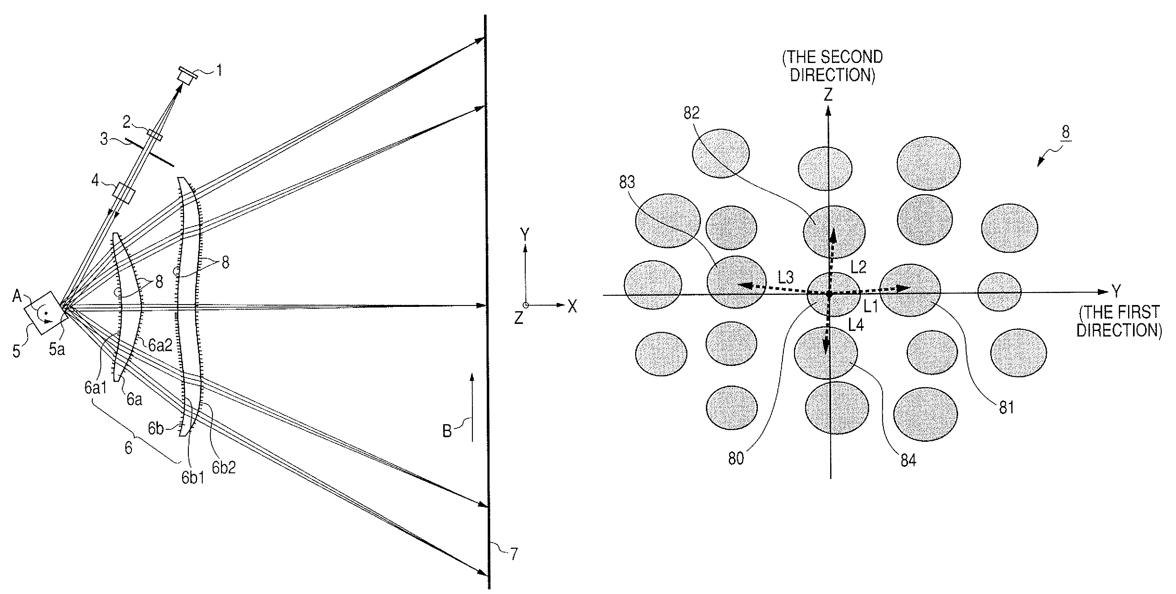
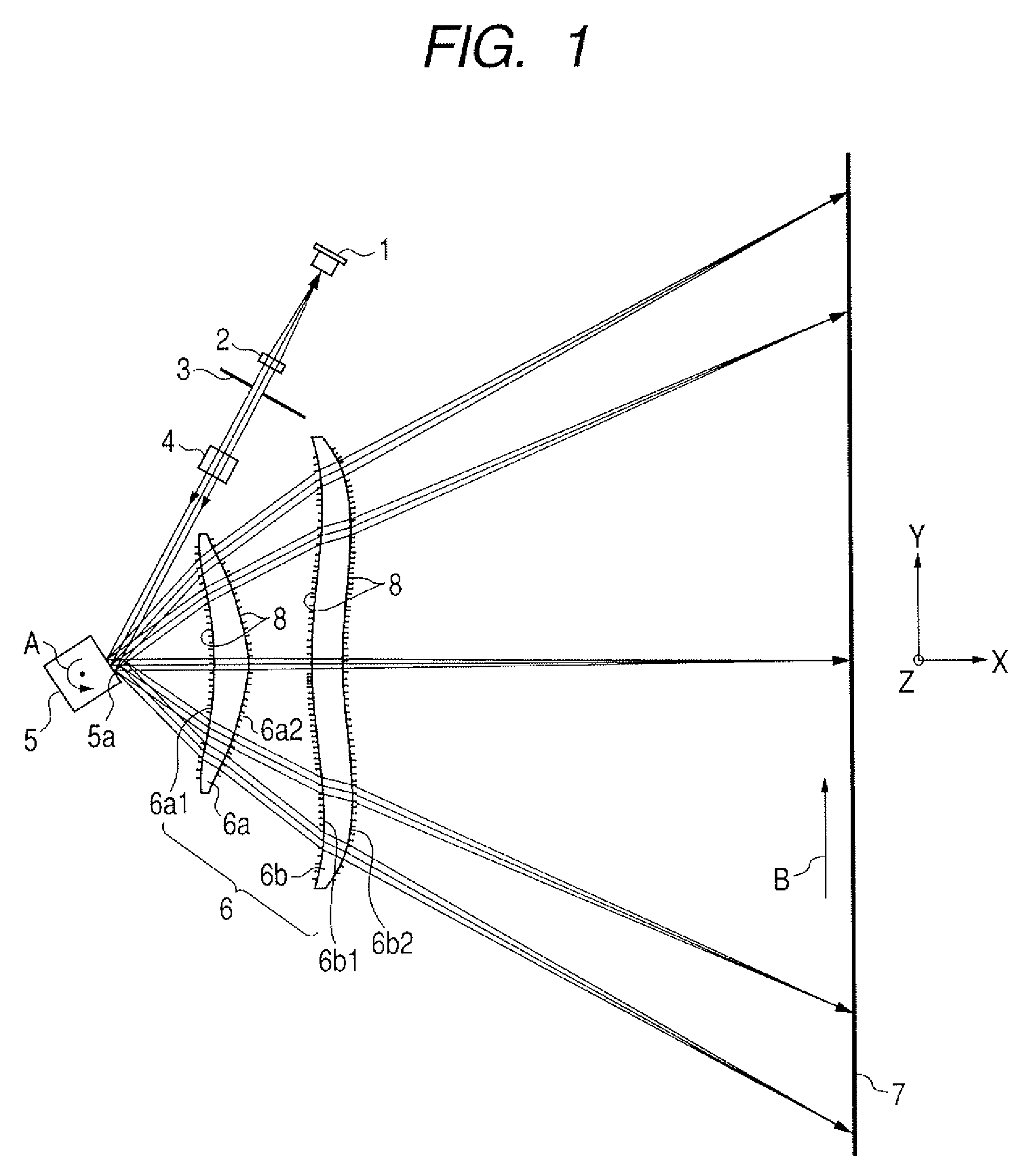
[0077]Next, Embodiment 1 in which the optical element according to the present invention is applied to an optical scanning device will be described with reference to FIGS. 1 to 6. FIG. 1 is a cross sectional view of a principle part of the optical scanning device in a main scanning direction (main scanning sectional view) according to Embodiment 1 of the present invention. In FIG. 1, a Y-axis is set in a scanning direction ...

embodiment 2

[0136]Embodiment 2 of the present invention will be described with reference to FIGS. 7 to 13.

[0137]A point in this embodiment which is different from Embodiment 1 described earlier is that a subwave structure whose cross sectional shape is a deformed circle is formed in a convex shape. Other structures and optical functions are substantially identical to those of Embodiment 1 and thus the same effect is obtained.

[0138]That is, in this embodiment, each of the incident surface 6a1 of the first imaging lens 6a in the imaging optical system 6, the exit surface 6a2 thereof, the incident surface 6b1 of the second imaging lens 6b therein, and the exit surface 6b2 thereof has a special aspherical shape as a base shape. A subwave structural grating 89 shown in FIGS. 7 to 9 is formed in each of the surfaces.

[0139]Therefore, reflectance (and transmittance) can be arbitrarily controlled in this embodiment. Thus, Fresnel (surface) reflection caused on each of the incident surface 6a1 of the fir...


PUM


Abstract

Provided is an optical element capable of reducing Fresnel (surface) reflection on a lens surface which causes flare or ghost, an optical system including the optical element, and an optical scanning device including the optical element. The optical element includes: a plurality of two-dimensionally arranged subwave structures having an anti-reflection function, and in the optical element when directions orthogonal to each other within a plane including a tangent of a vertex of the optical surface are set as a first and second directions, each of distances between the subwave structures changes in at least one of the first and second directions, and an arbitrary subwave structure is located with a state in which a distance between the arbitrary subwave structure and one of the subwave structures closest to the arbitrary subwave structure is shorter than ½ of an average wavelength of the light beam incident on the optical surface.

Description

BACKGROUND OF THE INVENTION[0001]1. Field of the Invention[0002]The present invention relates to an optical element having an anti-reflection function and optical scanning device using the optical element. In particular, the present invention is suitable for an optical system of an image forming apparatus such as a laser beam printer, a digital copying machine, or a multifunction printer, which has, for example, an electrophotographic process, and employs a structure in which a light beam emitted from a light source means is deflected by an optical deflector (deflecting means) to optically scan a surface to be scanned through an imaging optical system. The optical system includes an optical element which has an fθ characteristic and in which a subwave structural grating is provided, thereby recording image information.[0003]2. Related Background Art[0004]In a conventional scanning optical apparatus such as a laser beam printer (LBP), a light beam modulated in accordance with an imag...

Claims


Application Information

Patent Timeline
Patent Type & Authority Patents(United States)
IPC IPC(8): G02B26/08
CPCG02B1/118G02B5/1809G02B26/125G02B27/0018
Inventor KIMURA, KAZUMI
Owner CANON KK
Why Eureka
Try Eureka